This thread has been locked.

If you have a related question, please click the "Ask a related question" button in the top right corner. The newly created question will be automatically linked to this question.

INA240: INA240 Gain Error issue

Part Number: INA240


Hi,

  Customer designed Battery testing solution used current sensing IN240A3 .the schematic as below,the design spec is output 60A current and the accurancy is 0.1%, so the output current error is less than 60mA. From INA240A3 datasheet,(the Gain is 100V/V, and gain error  type value is 0.05% and max value is 0.2%). Now when power up the system,  input 1A current source(50mV) at DCCURR+/DCCURR- ,there is a output error about 2~3mV voltage at output side, it means 60mA current error at 3mV voltage error. and it will beyond the system spec. when operation time. At same condition, replaced TI INA301A3( Gain is 100V/V, and max gain error is 0.1%) get the same result. Customer want to calibrate the gain error, but confused the gain error is not stable and can't set the gain coeffiecient .Customer want to know how to fixed it. thanks!

  • Elan,

    The schematics you attached did not come through on the post.  I think that perhaps you tried to simply paste the graphics into the text editor here instead of using the paperclip or polaroid buttons to attach them? In any case, would you mind sending them again using the attachment buttons in the advanced editor?

    Please make sure the schematic and/or reply post includes the bus voltage, supply voltage and shunt resistor value.

  • Hi  Jason,

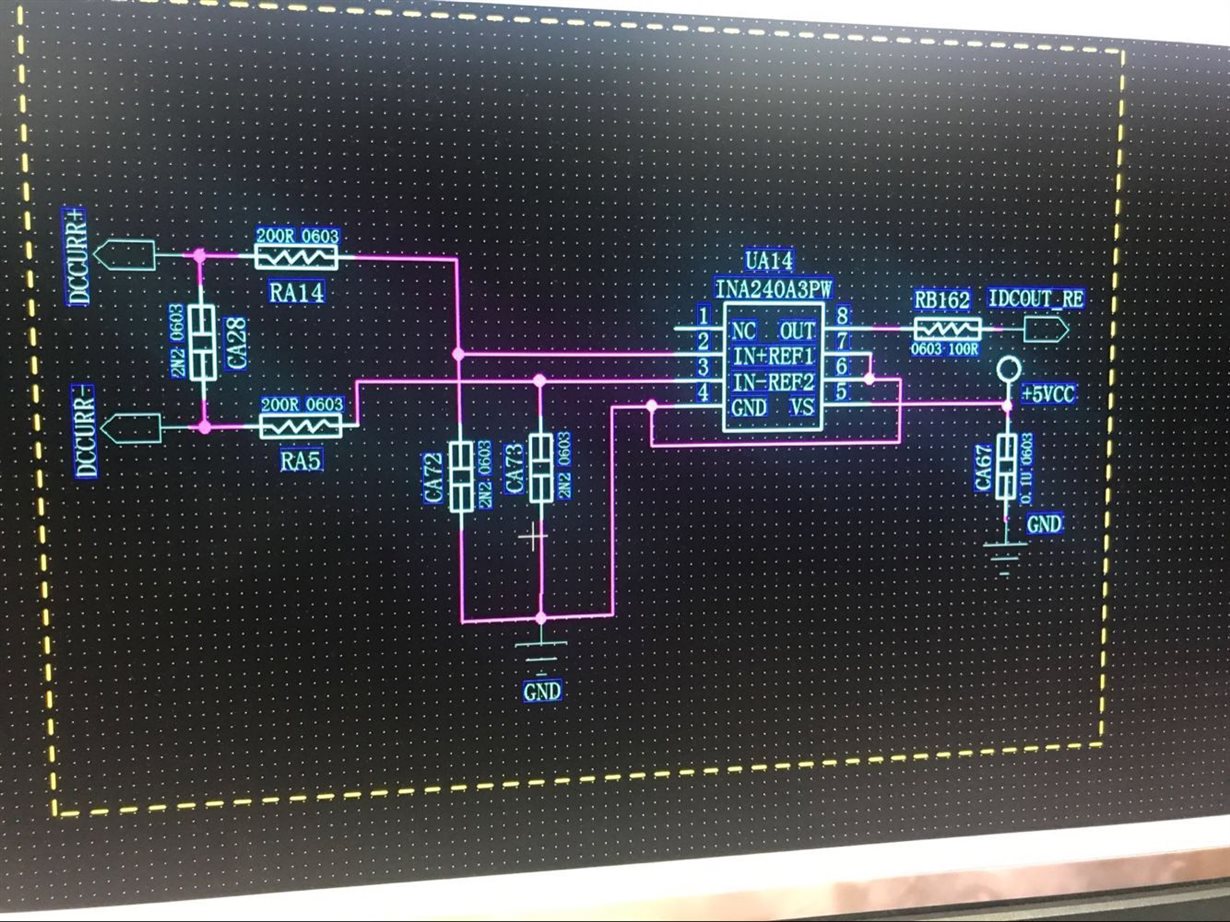
      attached schematic for you reference.customer just testing this part circuit and get the same result as previous descripition. please kindly help . thanks!

  • elan,

    This schematic is interesting - the input filter is different from the one we usually recommend.  Usually we put CA28 on the amplifier side of RA14 and RA5, and we don't usually include CA72 and CA73.  Without knowing more about the application, here is the input filter we typically recommend:

    So let me run through the calculations you have given -

    With a 5V supply and a gain = 100 V/V, the maximum input voltage is 50mV, but remember also that the maximum output could be as low as Vs-200mV, so the actual max output voltage is 4.8V, meaning the largest input voltage to guarantee you stay in the linear range would be just 48mV.  The swing to GND of the output could be as high as GND+10mV, so the minimum sense voltage you could see an output with would be 100uV.

    The Gain error spec is for Vout larger than 50mV and smaller than Vs-200mV, so actually, the input range you could use to stay in the linear range with the specified gain error would be 500uV-48mV, with Vs=5V.

    If you want to maximize your use of the input range, then you would need a sense resistor = 48mV/60A = 0.8mOhm.

    With that, the minimum current you could conceivably measure with the specified gain error would be 500uV/0.8mOhm = .625A.

    The gain error does not take into account the offset error, and offset error dominates the % error of the measurement at small Vsense voltages.  Vos, PSRR and CMRR all contribute to offset errors.  Assuming you're using a 12V Bus voltage and a 0.8mOhm resistor, this is kind of what the error curve will look like.  It's not necessarily for the A3 version, but it gives you the idea.  I added a red line that shows you where 0.625A is, so you can see how much the offset will affect the error of that measurement.

    I hope this clarifies how different error sources can affect the measurement accuracy.  I believe it can be calibrated out somewhat on a device/system level with a multi-point calibration routine.