This thread has been locked.

If you have a related question, please click the "Ask a related question" button in the top right corner. The newly created question will be automatically linked to this question.

OPA4314: OPA4314

Part Number: OPA4314
Other Parts Discussed in Thread: TINA-TI

Hello,

For our application, we must design a simple filtering circuit consisting of a 50/60Hz notch filter to remove ground noise, followed by a 10KHz low pass filter.

The design parameters are:

VCC: 3.3V - battery powered device

Frequency range of interest: 100 Hz to 10 KHz

Vin: 0 to 3.3VPP sine wave

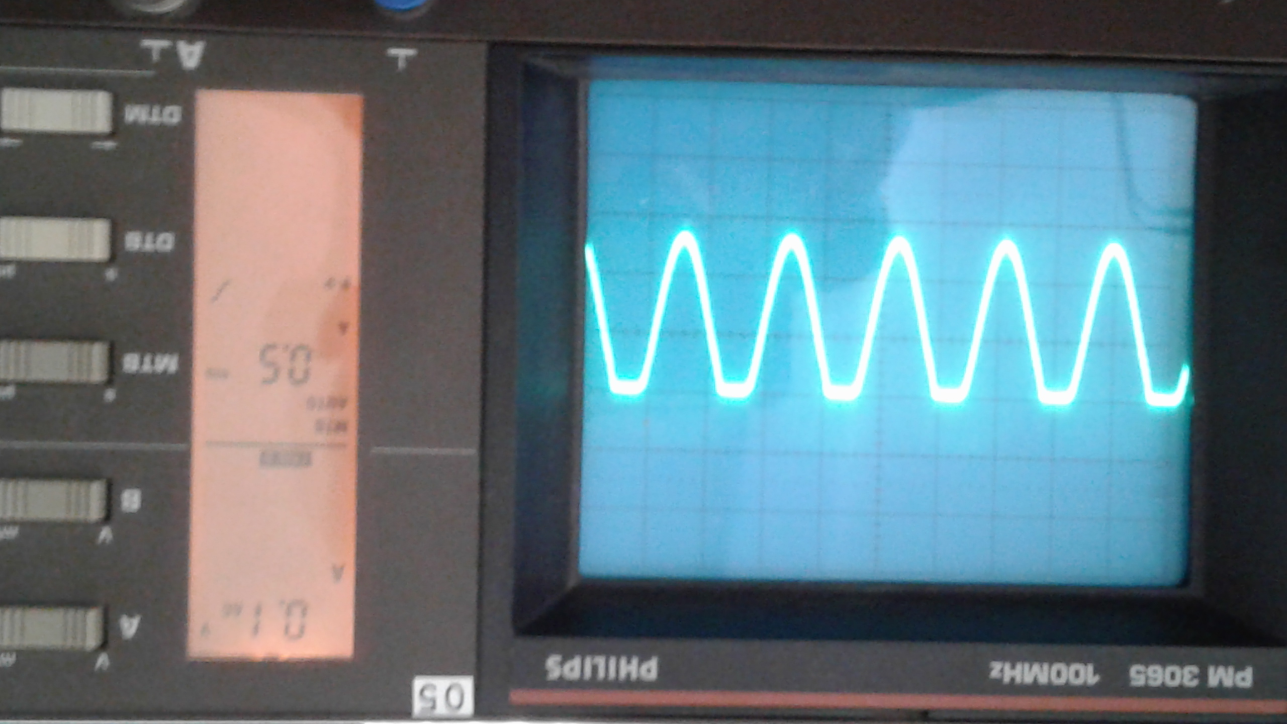
In the attached TINA file, the filters has been calculated with Filter Pro. Using an OPA414, when the input signal amplitude reach around 300 mVPP, the 50/60Hz notch filter output start distorsion.

The same issue appears using a Twin T 50 50/60Hz notch filter using the OPA414 implemented on the PCB prototype's. So I suppose that this op amp is not the right choice and I should really appreciate your recommendation for this application.

Awaiting your soon reply, I already thank you.

Kind Regards,

Guy BERWART

50Hz notch filter + 10 KHz Low Pass Filter.TSC

  • Guy,

    Tim will look at this on Monday. I noticed that the 1st and 2nd op amp have no DC bias on the non-inverting input so this voltage will float around and cause clipping issues (if it works at all).
  • Hi Ron,

    Thank you for your reply.

    Attached, you will find the schematic of the 50 Hz Twin T notch filter that I was talking about in my previous post and which is implemented on the prototype PCB's + its output picture with 300 mVPP signal input.

    Even it works well with TINA, I noticed that the OPA 314 is clipping anyway and that the clipping start level is different from a board to an other...

    Thank you again for your support!

    Kind Regards,

    Guy

    50Hz Twin T notch filter + 10 KHz Low Pass Filter.TSC

  • Hello Guy,

    I apologize for the delay in a response regarding your issue.

    As Ron mentioned, there is no DC bias path to the non-inverting input of the 1st amplifier. This will cause the input to float and potentially cause clipping issues like you are seeing. If you place a probe (in TINA-TI) on the non-inverting input and run a DC analysis you will see it reads ~1.7V in your current solution. However, this voltage isn't generated from anything because the bias voltage coming from the bias voltage buffer (U7) is blocked by C25, C26, and C27 before it gets to the input of the amplifier. The 1.7V is likely the result of the input not having a DC bias path. One possible solution is to bias the non-inverting input up through a 100k resistor using a voltage divider on the power supply and an amplifier to buffer it. Please see the attached TINA-TI file and let me know if this solution will work for you.

    Thank you,

    Tim Claycomb

    50Hz Twin T notch filter + 10 KHz Low Pass Filter_TI.TSC

  • Hello Tim,

    Effectively I forgot the bias DC bias path to the non inverting input of the 1st amplifier, I am sorry.
    Now, your design works very well even if the 50 Hz notch filter bandwith is a little bit larger than in my design (+/- 100 Hz on both sides) and the attenuation reaches more than -50 dB instead of -35 dB in my design.

    Thank you again for your support!

    Kind Regards,

    Guy