This thread has been locked.

If you have a related question, please click the "Ask a related question" button in the top right corner. The newly created question will be automatically linked to this question.

OPA551: High idle current consumption

Part Number: OPA551

Hi,

We are using the OPA551 (SO-8 package) to generate a waveform (controlled via DAC) of +/- 24V. However, when we connect the +24V from the power supply to V+ (pin 7), and -24V to V- (pin1, 4 and 5) the power consumption if about 140mA, with or without any sort of input. Our output current is limited to just 2mA. The IC is decoupled with a 100nF and 10nF capacitor.

In the end the OPA551 works perfect, but the only problem is the power consumption which is extremely high to be honest. Is there an easy solution for this problem? I've already tried a few chips, but all with the same result.

Thanks!

- Raoul

  • Hi Raoul,

    140mA is roughly 20x what the quiescent current should be for the OPA551. Could you please provide a copy of the schematic so we can verify there are no configuration issues? Additionally, I would suggest taking a look at the output of the amplifier with a high impedance oscilloscope probe to see if there are any oscillations as this can significantly increase power consumption.

  • Hi Zak,

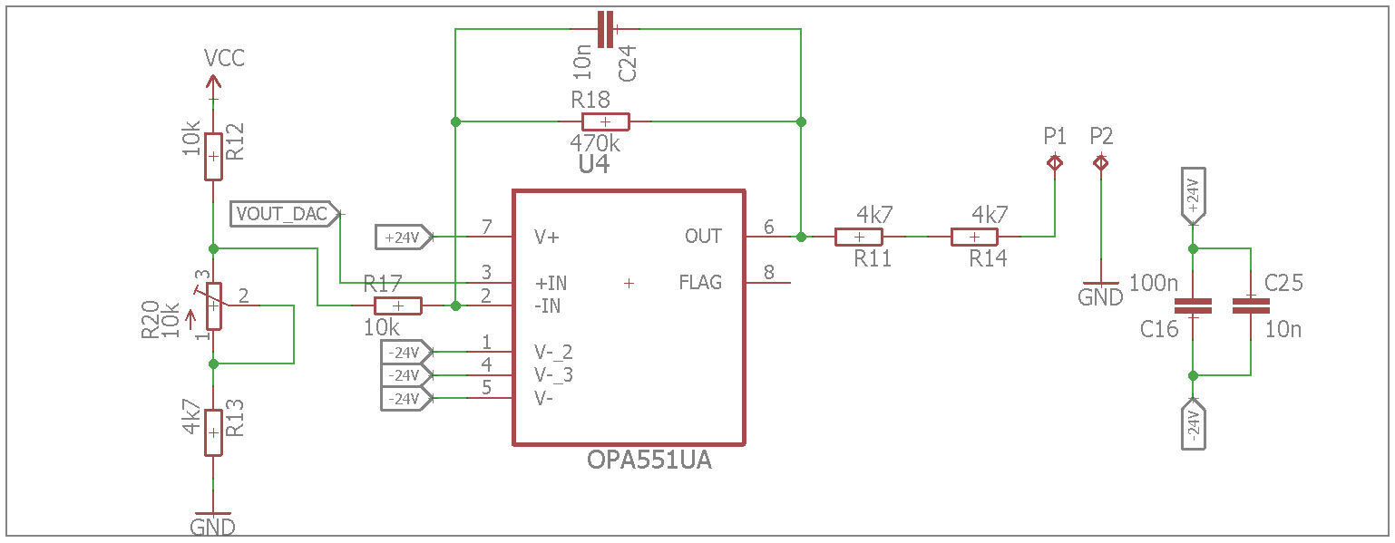
    Thanks for your quick reply. Please find the schematic below.

    Later this week I will take another close look at the circuit with an oscilloscope..

  • Raoul,

    Thank you for sharing this. Could you please clarify what Vcc is in the above schematic and what output voltage you see when the op amp is sinking 140mA?

    Additionally, for proper power supply decoupling you should place capacitors to ground on each of the power supply rails instead of capacitors between the two rails.
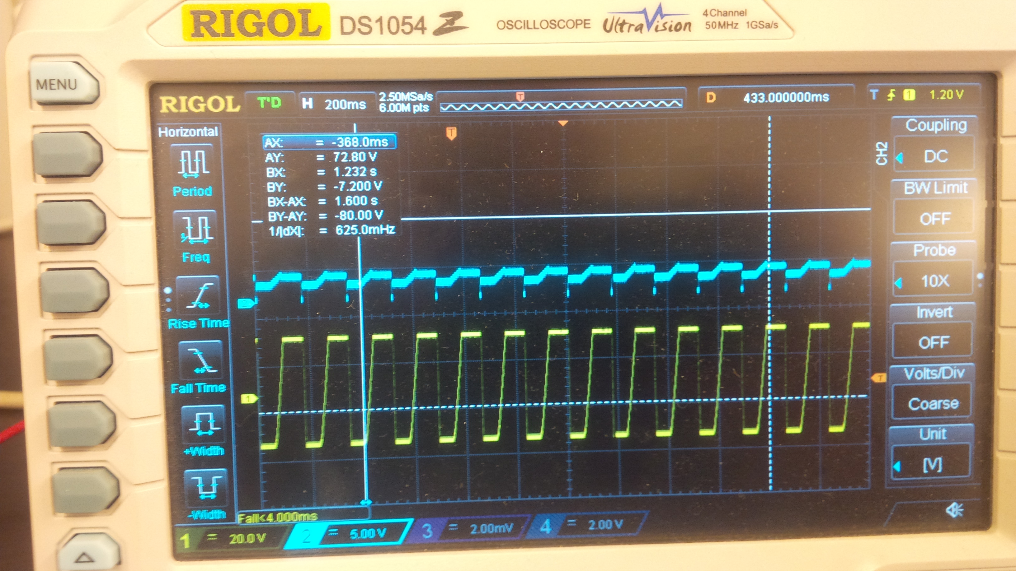
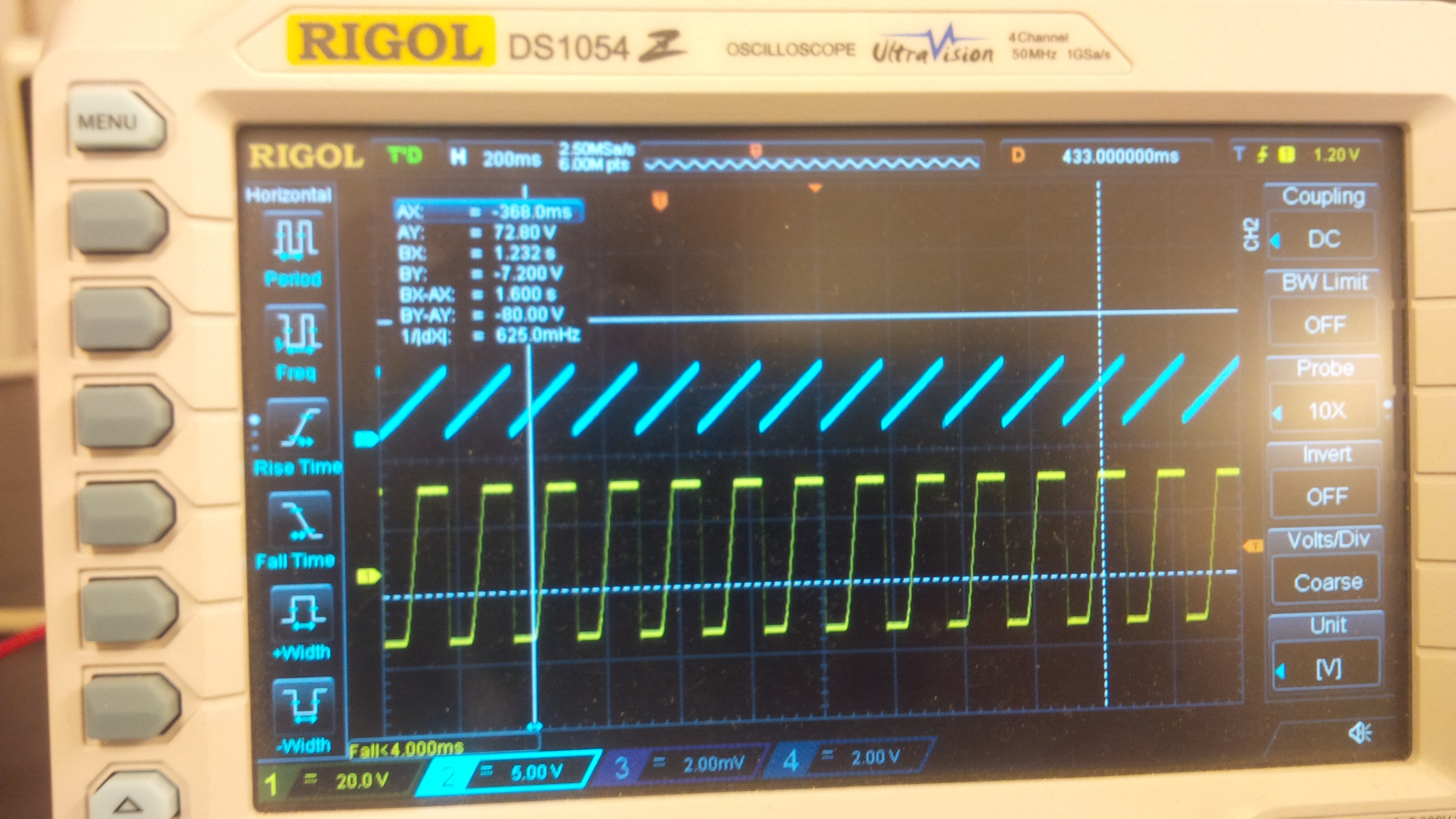
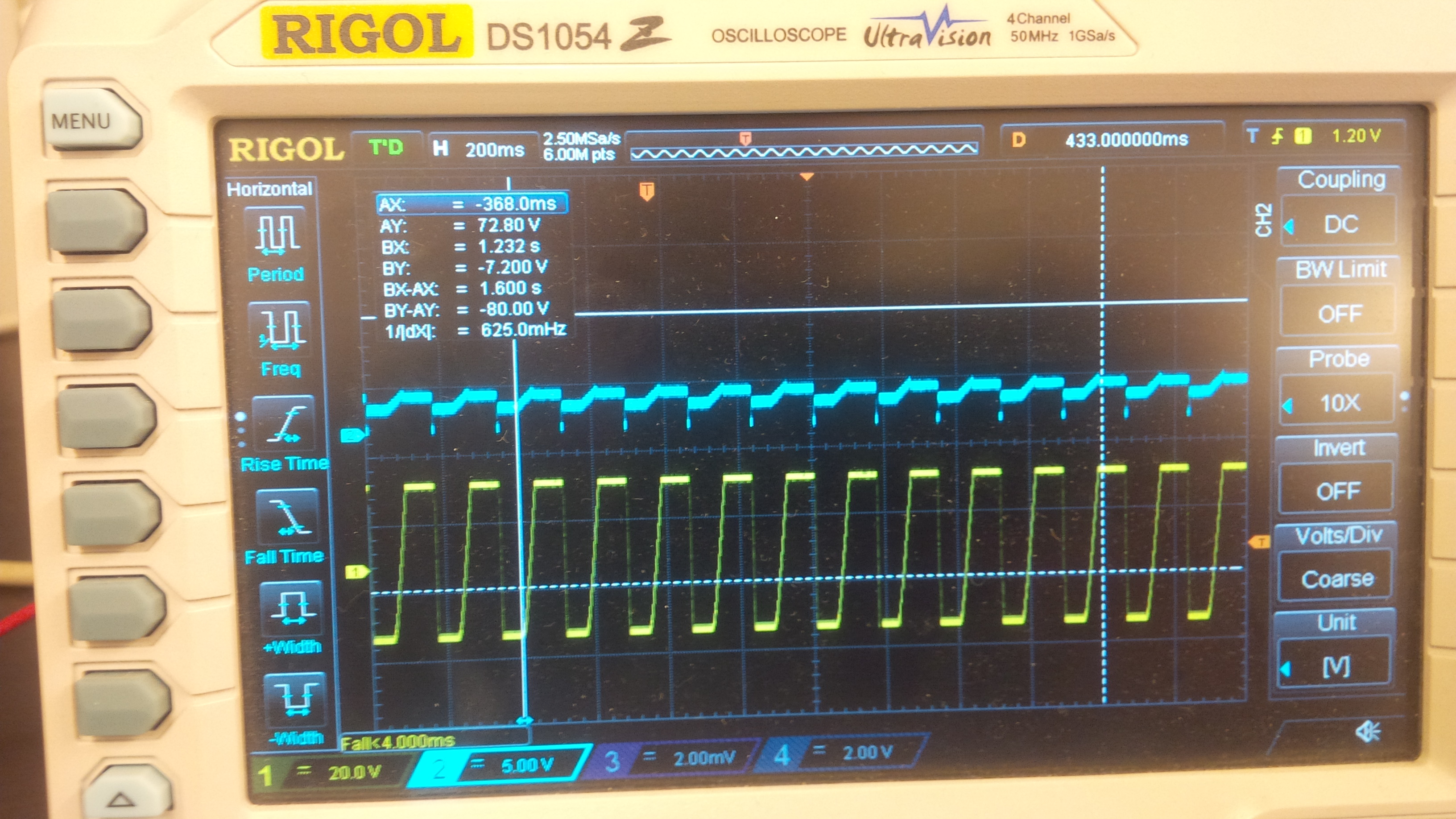
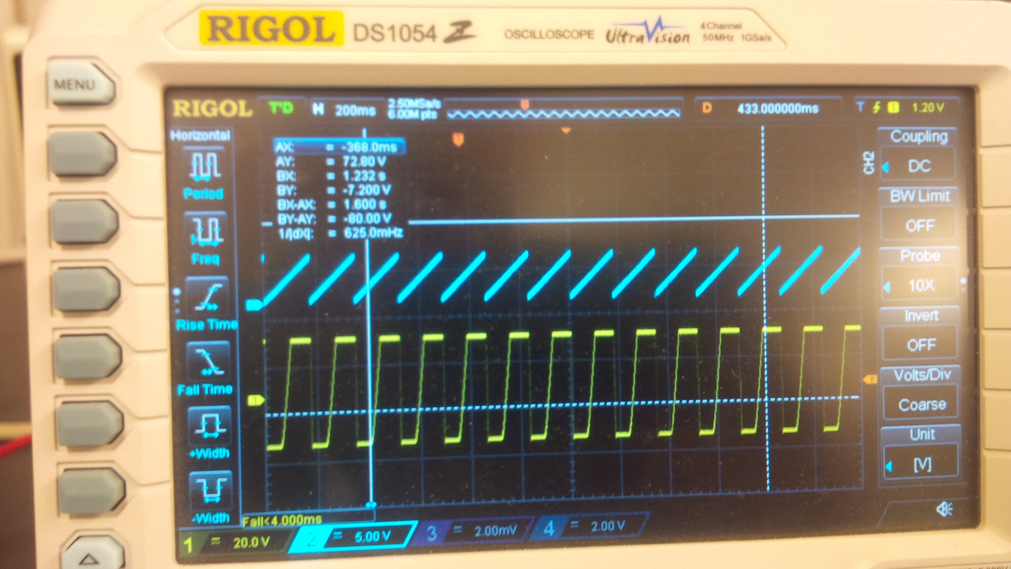
  • Feedback on Pin 2 (-IN) vs Output  :

    DAC Control voltage on Pin 3 (+IN)

    I also removed the 100nF capacitor between the +24V and -24V rail, and replaced it with 2 capacitors going from +24V -> 0V, and -24V -> 0V respectively. The current consumption did not decrease unfortunately.

    Also, VCC is 5V.

    In the pictures above the only load is the oscilloscope probe, which should be about 1M Ohm.

  • Ah, looks like the op-amp was not the problem after all. Im the circuit we use a 3.3V -> 5V inductorless converter, and it seems that it can't perform as well as expected.

    I just did a quick test and put 5V on the PCB (instead of the converter), and current consumption is down to about 80mA which we expected.
  • Glad you were able to resolve the issue! Let us know if there is anything else we can assist with.