Part Number: LOG114
Support Path: /Product/Development and troubleshooting/
Hello,
I have a problem of precision with LOG114 logarithmic amplifier.
These are my data:
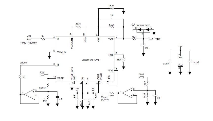
V + = 5V
V- = -5V
VCMIN = 0V (GND)
I2 = 64uA (Iref)
Vcom = 1.44V
By raising the current I1 from 2uA to 900uA on the VLOGOUT output there is an increasing offset, compared to the theoretical value, ranging from 26mV to 90mV (with the growth of I1).
At the same time at I1 input (pin 4) a rising offset (with I1), that takes a few mVs to at least 25 ÷ 30mV, is created ... and I think it is the reason for the problem.
Why does the offset input to amplifier A1 go beyond the 4mV max specification?
PS: the input of the amplifier A2 has the same behavior ...
Thank you and goodbye.