This thread has been locked.

If you have a related question, please click the "Ask a related question" button in the top right corner. The newly created question will be automatically linked to this question.

LMH6552: Bad step response

Part Number: LMH6552

Hello

I have a deferential 50R source. I want to sample it using LMH6552 and an high speed ADC.

But there is an odd problem.

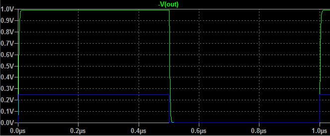
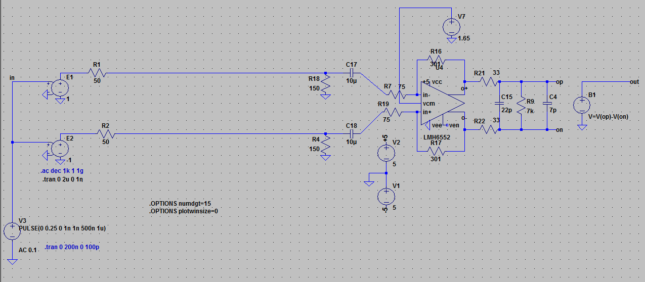
when I don't put any LPF between the sorce and the LMH6552 the step response is very good : 
But when I put a LPF with fc=15MHz between the Source and the LMH6552, the step response is not good. I couldn't solve this issue by using some capacitors on the FDA's feedback path.
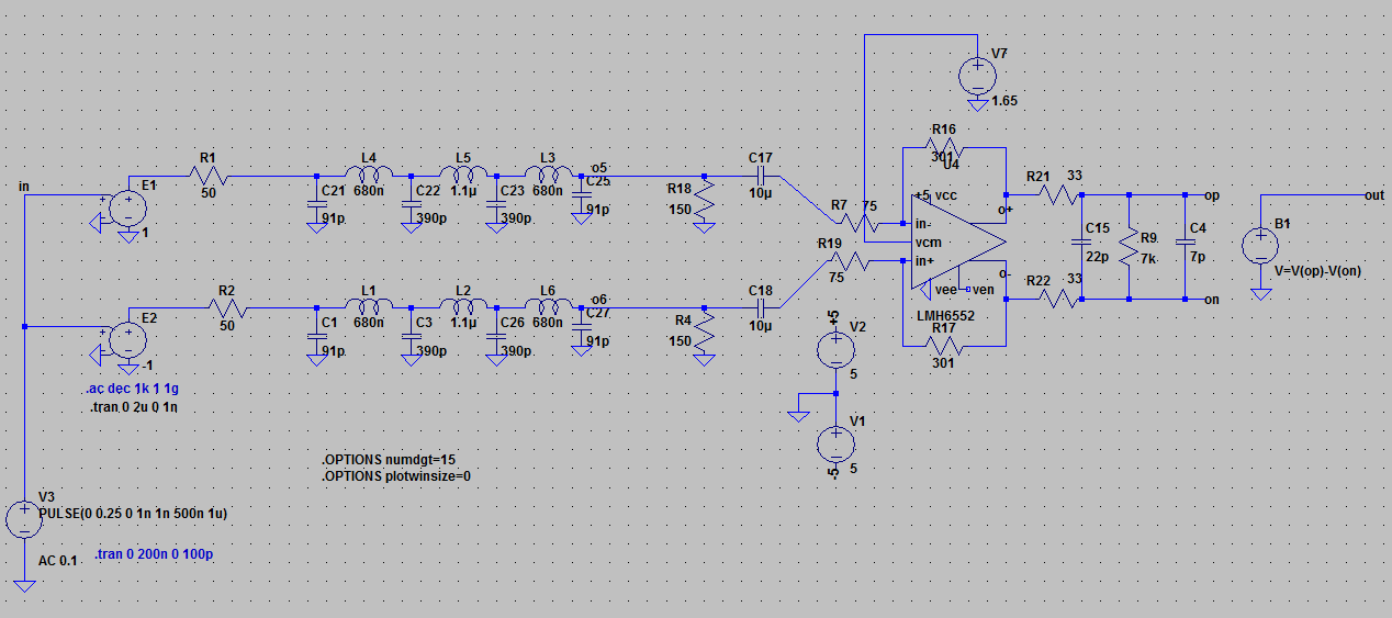
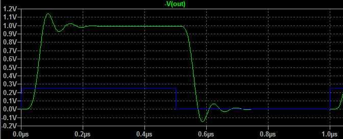
even when I buffer the source with an unity gain buffer, the problem is repeated again. I checked the signal on the 150R resistors and I found this peaking comes from here!

what should I do?

I think the response in not Butterworth! I should filter the noisy source like above.

Regards

  • Hi,

    I think you are right that the response is not Butterworth anymore by adding the low pass filter in-between the source and the LMH6552 input. You are seeing an overshoot in the time domain pulse response probably because of that. Including a filter at the LMH6552 input causes the gain stage impedance to go low beyond the filter -3dB cut-off frequency, which effectively peaks up the amplifier roll-off slightly and not giving the Butter-worth filter response. However, if the filter were to be at the amplifier output, the relatively low output impedance of the amplifier helps in providing a stable frequency response for the filter. This is one of the reason as to why its beneficial to have the filter constructed at the amplifier output instead of the input. 

    However, to fix the circuit you could try to reduce the pulse response overshoot by including a feedback cap across Rf resistors, as shown in the below image. The cap across the input pins is present for stability purposes. Also, the input filter values have been changed to get a less damped frequency response, as you can see from the lesser overshoot in the time domain pulse. 

    Best Regards,

    Rohit

  • Thanks for your attention and your remarks 

    Did you check the close loop response? 3dB cut-off frequency of the circuit is 10MHz due to putting large capacitor in the feedback of the FDA :)

    I can remove the input filter and put 5th order LPF after the FDA. but there is problem! non of the real inductors are ideal :| it's not easy to choose  inductors.

  • Hi,

    It should be possible to re-adjust the cut-off frequency of the input filter to say 30MHz and reduce the feedback cap accordingly to give 15MHz of overall f-3dB frequency response without an overshoot. I believe this is something that you could try?

    Best Regards,
    Rohit
  • it's an interesting problem!

    the main usage of the input filter is Noise reduction.

    I should put a 7th or more order LPF with f3dB 15MHz. there is no way.

    even in a simple circuit like below:

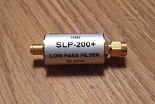
    (50R source)------>Cable------> (15MHz 50R in-Line filter)----> (50R terminated)

    if we want to check the step response the problem appears again!

    without the filter the step response is good but with a LPF the step response is bad.

    actually the source produces multi-tone signals. (Like a MultiSine or a Chirp).

    if I want to use a LPF like above there is a %15 overshoot.

    is it a Stable circuit in a real world? (I know the phase Margin and Q factor).

    even is it an issue when I work with Multi-tone signals? or it is important when I have a pulse signals?

    Best Regards

  • Dear

    actually I have a 3rd order filter after the FDA (befor the ADC). this is actually an anti aliasing filter. (AAF or RFI filter)

    now can I use a Digital FIR filter instead of an high order LPF filter at the input of the FDA? (I want to improve the SNR and THD to have a better ENOB parameter.)

    if I use such method there is no stability issues in the Analog circuit.

    I'm so frustrated after many month :|

    Thanks

  • Hi xyz xyz,

    Improving step response and limiting broadband noise is a direct tradeoff. Think of the step response as a square wave Fourier series with a fundamental frequency of 1MHz. A 15MHz LPF will limit your Fourier series to 7 harmonics. The lower your LPF cutoff, the fewer harmonics your Fourier series will have, and the greater your overshoot. You will have to determine the appropriate balance for your application.

    Best regards,

    Sean
  • Dear
    Exactly, if we filter more harmonics, even the 3rd order, it will be a sine signal completely.
    actually this is the nature of filtering and Fourier theory...

    **I have concern about the stability of the circuit.**
    usually when I want to check the stability of a circuit, I check the Phase Margin and the step response. in a real circuit I only check the step response.

    I work with Multi tone and Chirp (Linear FM) signals.
    especially the Narrow band circuits use BPF or SAW filters. I think the step response is non sense for them.

    Summary: I think the circuit with LMH6652 is stable! the amount of overshoot without the Filter is zero.
    now when I put a filter, actually the input signal of LMH6652 is a Pulse signal with %15 overshoot! and LMH6652 transfers it to the output without any problem. we can apply a sine or any Arbitrary signals to the input of LMH6652!
    I believe this is a misleading problem when we want to check the stability! :)
    but I should care about the signal's behavior and characteristics. I'm working on the impedance measurement.

    Best Regards