This thread has been locked.

If you have a related question, please click the "Ask a related question" button in the top right corner. The newly created question will be automatically linked to this question.

OPA567: output impedance in the PSpice model

Guru 20090 points
Part Number: OPA567
Other Parts Discussed in Thread: TINA-TI

Hello,

Is the OPA567 PSpice model included output impedance?

Our customer is using OPA567 PSpice model and they input DC signal, with G=1, RL=1ohm.
In the datasheet, the Output impedance of G=1, DC is 0.1ohm.
I think that the model is not included output impedance.

If the model is not included output impedance, could you please share the revised model of OPA567?

Best Regards,
Ryuji

  • Hello Ryuji,

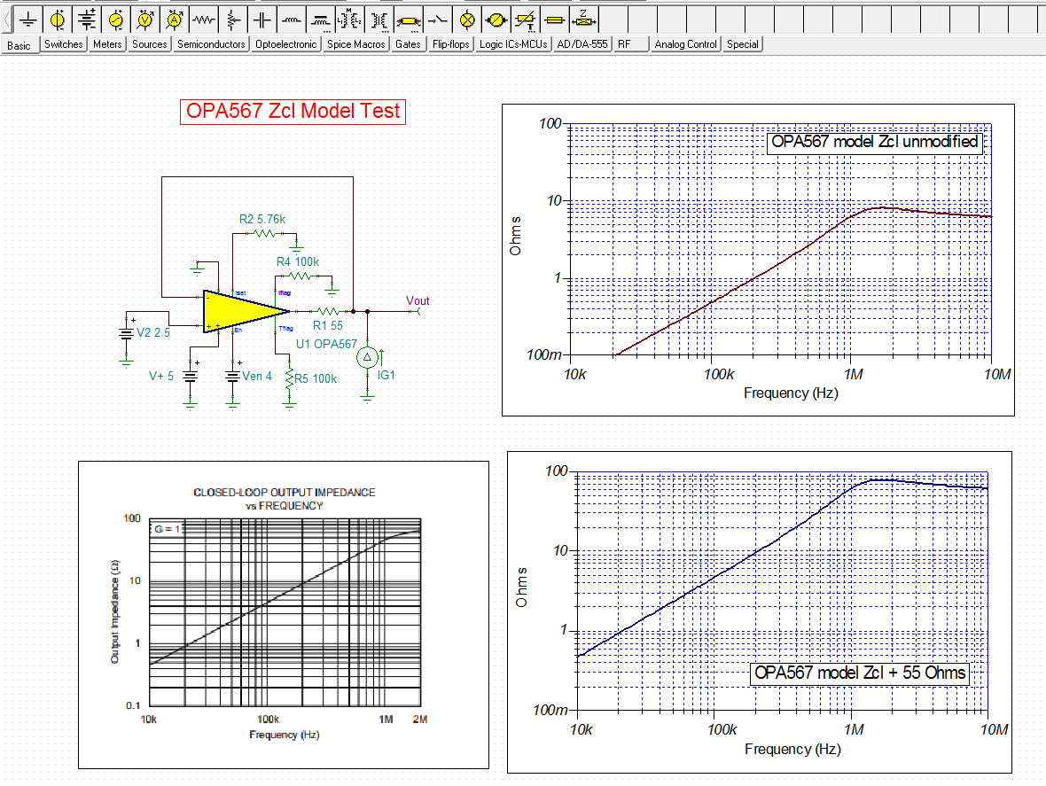
    I tested the OPA567 simulation model closed-loop output impedance Zcl, and compared it the graph on page 12 of the datasheet. The OPA567 model was set up in a closed-loop gain of +1 V/V, back driven with a current source, and the closed-loop otuput impedance swept across frequency. The results are summarized in the graphs shown below.

    The datasheet Zcl graph is shown in the lower left corner. This was used for comparison. The upper right graph is the Zcl produced by the unmodified simulation model. The curvature of this Zcl plot is very similar to the data sheet Zcl curve, but the impedance is shifted downward and is low at all frequencies.

    Adding about 55 Ohms of resistance directly in series with the OPA567 output moves the Zcl curve upward and the impedance values shown in this graph, and the datasheet graph match nicely. This can be seen when comparing points in the lower left and lower right graphs.

    I suggest adding the 55 Ohm resistor to the output as shown in the schematic, to any circuit you want to evaluate. Doing so will make any ac analysis, such as stability analysis, more accurate. However, the resistor should be set to 0 Ohms when driving a high current load. Otherwise the voltage drop across the resistor will become an issue.

    Regards, Thomas

    Precision Amplifiers Applications Engineering

  • Hello Thomas san,

    I appreciate your support.
    Could you please share the Zcl model test design?

    Best Regards,
    Ryuji
  • Hello Ryuji,

    I am not sure I understand what you are requesting?

    In my previous reponse I showed the TINA OPA567 Zcl test circuit in the upper left corner of the tINA diagram. It consists of an OPA567 unity gain amplifier circuit, where the output is back driven by an ac current source. The Analysis tab is selected in TINA, followed by AC Transfer Characteristic. Select the Gain checkbox and run the simulation.

    When the simulation is complete and the graph is presented, click on the vertical scale and chnage the title fro GAIN (dB) to Ohms. Also, change the scale to a log scale. You can set limits as needed to best view the Zcl vs. frequency information.

    Regards, Thomas

    Precision Amplifiers Applications Engineering

  • Hello Thomas san,

    I appreciate your reply.
    I simulate from TINA-TI reference design and change the schematics as your recommended.
    However, I couldn't get the same result. Thus, I would like to get your simulation file.
    I attached my TINA-TI design. Could you please let me know if there is any wrong in the file?

    OPA567 zcl 55ohms.TSC

    Best Regards,
    Ryuji

  • Hello Ryuji,

    I do get the same OPA567 Zcl results when I use your TINA file. It just may be a matter of getting the scales set up correctly.

    I have attached my OPA567 TINA circuit file for you to try.

    Regards, Thomas

    Precision Amplifiers Applications Engineering

    OPA567 Zcl Test 01.TSC

  • Hello Thomas san,

    RL - 1 ohm and Vswing = 2 Vpp, It means over 1A load.
    2 V output capability is maintained at Vs = 2.7 V.
    It seems to mean less than 0.7 ohm up to 100 kHz.

  • Hello Thomas san,

    My name is Kodera. I am a circuit design engineer.
    Now, I am designing circuits using OPA567.

    Please check the graph in datasheet. --> "MAXIMUM OUTPUT VOLTAGE vs FREQUENCY"
    RL = 1 ohm and Vswing = 2 Vpp, It means over 1A load.
    2 V output capability is maintained at Vs = 2.7 V.
    It seems to mean less than 0.7 ohm to 100 kHz.

    It is incompatible with the impedance characteristic when inserting 55 Ω.
    I think there is a mistake in either characteristic graph.

    OPA567 has excellent performance of 2A output capability. I do not think there is 0.45ohm at 10 kHz...
    I think the original spice model is correct. (No 55ohm insertion)
    What do you think?

    Best Regards,
    Satoshi Kodera
  • Hello Kodera-san,

    The simulation model for the OPA567 needs to be redesigned because the current model does not produce the correct open-loop (Zo), and closed-loop output (Zcl) impedances. Those parameters are correctly set in our newer model developments, but many of the older models like the OPA567 didn't benefit from what we have learned about Zo across the years. We are aware of the need for a better OPA567 model, but many other models are in the queue ahead of it so there won't be a new one anytime soon.

    Meanwhile, The current model can be used successfully for general circuit simulation, and stability analyses. However, the model needs to be applied differently for those two cases:

    1. General simulations - Use the OPA567 without the addition of the 55 Ohm series output resistor. That will allow the OPA567 model to be simulated at high current levels. The voltage drop across a 55 Ohm resistor would be too great to allow for accurate circuit simulation.
    2. Stability analysis - Use the OPA567 model with the 55 Ohm series output resistor in place. The worst case phase margin degradation occurs with the highest open-loop output impedance Zo, and that occurs at very low output current levels. Don't try and use the model to deliver high output current when the 55 Ohm resistor is in the circuit.

    Please understand that the 55 Ohm resistor resides within the feedback loop and looking back into output, the Zo will be the original value in the model, plus 55 Ohms divided by the loop gain. The loop gain is the difference betwen the open-loop gain and the closed-loop gain at any particular frequency. Therefore, if the loop gain is for example 60 dB (1000 V/V), then the resistance it adds to Zo is 55 Ohms/1000, or 55 milliohms.

    Regards, Thomas

    Precision Amplifiers Applications Engineering

  • Hello Thomas san,

    Thanks for your quick reply.

    I understood the characteristics and the situation of OPA567 model.

    By output current (eg above or below Quiescent Current), I imagine that It has highly dependent Iout vs Impedance characteristic.

    Iout < +/- Quiescent Current ==> Hi impedance (near 45ohm at 1.2MHz, 1ohm at 20kHz)
    Iout > +/- Quiescent Current ==> Lo impedance for current drive (6ohm? less than at 1.2MHz, 0.1ohm at 20kHz)
    Is this recognition correct? Especially I am concerned about impedance around 10 kHz to 20kHz.

    >The worst case phase margin degradation occurs with the highest open-loop output impedance Zo,
    >and that occurs at very low output current levels.

    How much is "very low output current"? (Several mA --> eg 10mA)
    We expect that low impedance can be maintained with a constant current or more.
    Our designing applications always have load currents of over 80 mA (Constant current source).
    A dummy load can be given if necessary.

    Please tell us if there is a way to keep the impedance low.

    Thanks

    Best Regards,
    Satoshi Kodera
  • Hello Kodera-san,

    The only information that we have about Zcl is that provided on data sheet page. The graph supports when 12 Iout < +/- Quiescent Current ==> Hi impedance (near 45ohm at 1.2MHz, 1ohm at 20kHz). We do know that the open-loop output impedance (Zo) and closed-loop output impedance (Zcl) both move lower as the output sources/sinks an increasingly larger output current. Based on the same kind of measurements for newer op amps the quescient current case produces the highest Zo, and the curve will shift lower as the output provides load current.

    Ten to 20 kHz is at the low end of the Zo graph and we can see that the Zo is an Ohm, or less, and it should be a fraction of an Ohm at the 80 mA output current level.

    Regards, Thomas

    Precision Amplifiers Applications Engineering

  • Hello Thomas san,

    Thanks for your reply.

    I understood the following.
    - In the quiescent current case, Z becomes impedance high.
    - Zo and Zcl both move lower as the output current an increasingly larger.

    We will confirm the dependency by experiment.

    Thank you very much for providing the information.

    Best Regards,
    Satoshi Kodera
  • Kodera-san,

    Thank you for the feedback. Do let me know what you find regarding the OPA567 Zcl in your 80 mA current source application. I would be interested in seeing how it works out.

    Regards, Thomas
    Precision Amplifiers Applications Engineering