This thread has been locked.

If you have a related question, please click the "Ask a related question" button in the top right corner. The newly created question will be automatically linked to this question.

INA138: INA138 Curren sensing problem

Part Number: INA138
Other Parts Discussed in Thread: TPS22810, LMP7721, IVC102, DDC232, DDC112, DDC264, LMP7711

Dear all,

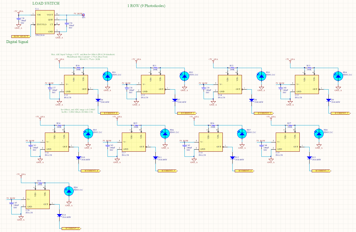
I am having problem reading current using INA138.  I have an array of photodiodes (see attached  schematics). The phodiode is PD93-21C/TR8, Digikey code 1080-1374-1-ND. The array is formed of 9 columns by 7 rows. To read photodiodes current I am using INA138. Every photodiode has its own INA138 and sensing resistor (RS). To read every current photodiode I power indiividual row using TPS22810 load switch IC, to supply power all INA138 beloging to the same row. In the output of INA138 there is a diode (1n4148) an all the diodes outputs are connected together and get into an ADC as in the picture 18 of the datasheet (Multiplexed Measurement Using Logic Signal for Power).

The maximum current throught photodiode is 1.77uA and then, using RS= 280K, maximum voltage drop in RS should be 0.5V and I should get an  Io= 100uA on pin 1 of INA138. With a RL= 21K the maximun voltage input to my ADC should be 2 Volts aprox.

If measure the voltage drop in RS when INA138 is switch off, I measure 0.04V (corresponding to 0.14uA, ambient light measurements) . However, once I supply power to the INA138 (digital high level on pin 3 of TPS22810) suddenly the drop in RS becomes 0.6V and the output on INA138 2.5Volts.

Can anyone tell me why when I switch on INA138 the voltage drop in RS goes to 0.6V? Are my calculus correct? Any idea what can be the problem?

Thanks in advance,

Joaquin.

  • Hi Joaquin,

    There is a bias current on each input of the INA138, of a few uA
    If the value of Rs is high enough, this current causes a voltage to develop across it, which the device then amplifies, based on its gain.

    Based on the above you should be able to take corrective measures. In essence, you need to redesign your circuit to accommodate a lower value sense resistor or use a device with lower bias input current, such as the LMP7721, with suitable feedback to obtain the required amplification level.

  • Joaquin,

    Carlos is correct - with this current shunt amplifier, the input bias current dwarfs the current you're trying to measure, making the measurement error astronomical. A device with a lower input bias current like an instrumentation amplifier is more suited to this application.

    You might look at the IVC102, it is primarily for photodiode applications and has an analog output, and has input bias currents in the fA.

    Another option is to use a device specifically for photodiode current measurement, like the DDC232. It has the ability to do a 160uS sample time and accumulate up to 350pC. If I'm not mistaken, 160uS x 1.7uA = 272pC, so you could use range 6 or 7 to measure the full scale of your photodiode current directly into an ADC and read out 20 bit digitized data with a serial interface. You could also attenuate the signal and use smaller ranges or longer integration times. Other devices in the DDC family have different channel counts and features, it may be worth it to investigate these products as an option.

    9 columns x 7 rows is 63 sensors. The DDC232 is built for daisy-chaining and has 32 inputs, so you could use two devices and read all 64 channels easily. The DDC264 is a single device solution that looks and feels the same. You're also welcome to use 32 x DDC112 devices, if that suits your application better - all can be daisy chained.
  • Thank you very much for your support.

    I have already a PCB with this INA 138, so change design will take time and money.  To avoid this, Do you think that if I change RS to a lower value It could work? The maximum current of the photodiode is 2uA. Which resistor would work to get and output on 0-2V range? Or it is not possible anyway?

    I think datasheet should recommended the current range appropiate to be used with these devices, I am new on this and I think it would help people like me.

    Thansk again,

    Joaquin.

  • Hello,
    Maybe you can help again to try to solve my problem.
    Assuming there is not solution to my problem with INA138 and changing RS, I guest that I must use an amplifier like LMP7721 (low input bias current of 20fA).
    To situate my problem now, let me explain again. My system is based in rows and columns of photodiodes. All photodiodes in a column share the input to a multiplexor and after the multiplexor I have an ADC. To measure the current of a photodiode in a column, I switched on the INA138 for that photodiode and switch off the rest of the INA138 for the photodiodes in the same column. As you can see im my schematic a diode (1N4148) blocked the current of the photodiode to be measued getting into the others INA138. I could do that because the output on INA138 is in current and not in voltage.

    I understand that if I have to use LMP7721, I should use it as a transimpedance amplifier, so the photodiode current is converted to a voltage. Should I convert this voltage to a current so I can use diodes to block current getting into others amplifier? Or if I use the voltage output of the transimpedance amplifier, and if I switch off the other amplifiers, the actual voltage to be measured will be affected?
    If I have to convert voltages to current, can you recomend me a circuit topology?
    Maybe is an easy question but I have not much experience on this.
    Thanks in advance,
    Joaquin.
  • Hi Joaquin,

    As Carlos and Jason mentioned above, there isn't really a way to make the INA138 work well in this application because regardless of how you scale RS, the bias currents are going to dominate your measurement.

    If the solutions Jason presented are not feasible, then a device like the LMP7721 could be configured for your application. You could try to use this as a transimpedance amplifier, but as you mentioned you lose the ability to use the diode OR configuration if you can't tolerate the voltage drop across the diodes. The difficulty is you can't assume that the output of the opamp will be high impedance in the unpowered state because of the ESD protection cells on the output. One possibility would be to use an opamp that has a disable feature that puts the output stage into a high impedance state, such as the LMP7711. Instead of cutting power to a row you could disable the outputs.

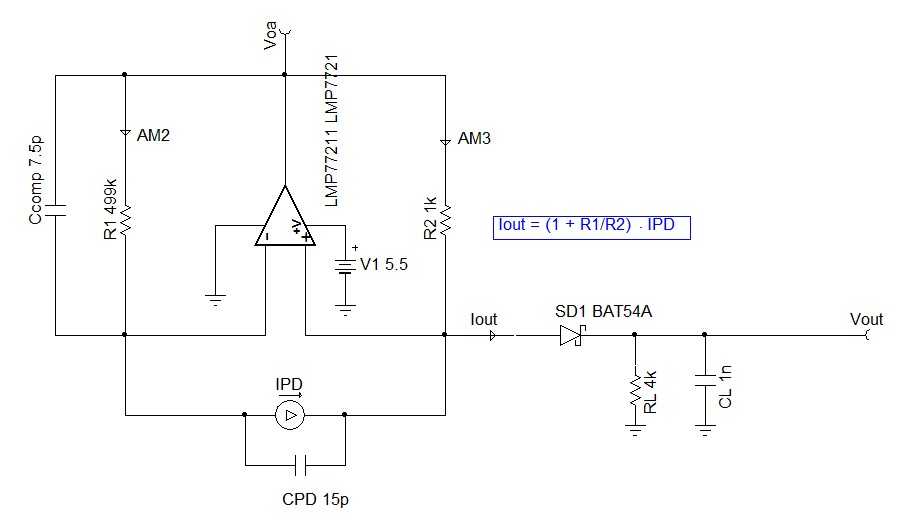
    Alternatively, you may consider using the LMP7721 as a current amplifier as opposed to a transimpedance amplifier. This would allow you to continue using the output diode. You just want to make sure to use a diode with a low forward voltage drop and low leakage. I have attached a concept design below. You would just need to scale things for what makes sense in your system.

    Photodiode Current Amplifier.TSC

    Do you have anything interfacing between the MUX and the ADC? Depending on the resolution of the converter and the acquisition time, you may consider adding a buffer to drive the ADC.

  • Thank you very much Zak and of course the rest of people who help me with this problem.

    This last post explain how solve the problem in a future new version of the board what I will redesign as soon as possible.

    Again, thank you.

    Regards,

    Joaquin.