This thread has been locked.

If you have a related question, please click the "Ask a related question" button in the top right corner. The newly created question will be automatically linked to this question.

TLE2064ID troubleshooting issue.

Other Parts Discussed in Thread: TLE2064

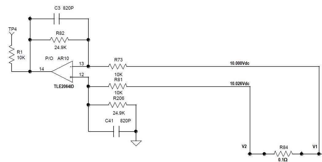
HI, team: My customer is  using TLE2064ID as a differential amplifier with 26mV across the input.  Approximately 10V at V  and 10.026 at V-
The rail voltages are set to  /-15V.
The gain analyzed in our circuit should be 2.5 but they are measuring 3.0.
I can send schematics.
We need help determining the possible cause.

He could not send the entire circuit but this is part of a closed loop system.  For troubleshooting purpose, he had removed a component so the circuit can be troubleshot as an open loop.

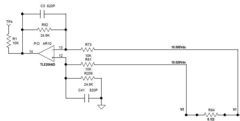
He measured the rail voltages to be ±15V.  V1 and V2 can vary depending on the input but it will typically be around 10V with V2 With Respect To V1 being around +26mV.  The gain of this circuit should be 2.5.  However, when he tested the circuit the gain was measured to be 3.

  • Hi Naser,

    There is nothing evident from a schematic standpoint that would explain an incorrect closed loop gain of 3 V/V vs. the expected gain of 2.5 V/V. The TLE2064 is configured as a difference amplifier with a 26 mV differential voltage applied across the inputs, obtained from the current shunt resistor. The expected output would be about +65 mV. The TLE2064 common-mode voltage (Vicr) extends from -11 to +13 V so the circuit having a +10 V Vicr would not violate that range.

    Since everything looks okay on the surface a less obvious factor may be at work. Check the output of the TLE2064 with a DSO (10x probe) and check for oscillation. I wouldn't expect the amplifier to be oscillating in this circuit, but if it is any measurement made with a DMM could be corrupted. DMMs will produce incorrect dc results if RF is present on their inputs.

    If that isn't, it we will have to look for something else.

    Regards, Thomas

    Precision Amplifiers Applications Engineering

  • Naser,

    Was the gain of 3 determined by looking at the output for two different shunt currents? Any other method will not be the gain.
    Keep in mind that your signal is 26mV and the 'noise' is 10V. S/N = 0.26%
    1% resistors are not good enough.
  • From customer:

    I checked the output of the op amp on a scope.  I did not see any oscillations.

     How the gain was measured: Based on the circuit below, I measured across V1 and V2 for the op amp input and TP4 for the output.

  • Naser,

    I suggest measuring output which I guess is 78 mV (26mV * 3). Then add a resistor from V1 to GND, for example 470 ohm that's an extra 21.3mA . Does Vout increase by 64mV (gain 3) or 53mV (gain 2.5)?

    Lets talk about error, if Vio was 7mV (worst case 25C) then output would have 3.5*7mV = 24.5mV output error
    What about a 1% error in those resistors in diff amp. 10V * 1% * 2.5 = 250mV error
    These potential errors are larger than the (3-2.5) * 26mV = 13mV error that was observed.
  • Hello Naser,

    It is highly improbable that a correctly functioning TLE2064 would be able to develop an incorrect, higher than expected closed-loop gain. Even if the open-loop gain (Aol) was at the low end, the gain would be less than the ideal 2.49 V/V for the circuit - not higher. The op amp isn't the source of the gain error.

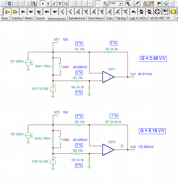
    The gain error is due to the deviation in the resistor values which can be as much as +/-1 % from ideal. Below I show a TINA comparison for the difference amplifier circuit where the first case uses ideal resistors (0 % deviation), and a second circuit where the feedback resistor is -1 % below ideal. The other three resistors remain ideal. An ideal op amp was used so that just the resistor effects could be realized.

    The ideal resistor case results in the expected gain of 2.49 V/V. But in the case where just the feedback resistor is reduced by 1 % a gain of 5.19 V/V is produced. I crunched through the math for the circuit with the same resistor values and obtained exactly the same gain result. This example is for just one non-ideal resistor so the possibilites for a wide range of different gains is a real design concern for this circuit. Likely, all of the resistors used in the actual circuit were relatively close to the ideal values resulting in the gain of 3 V/V, instead of something much higher or lower.

    If the user needs to achieve a gain that is closer to the desired 2.49 V/V, it is recommended that they select resistors having a tolerance of 0.1 %, or even 0.05 %. The cost is a bit more, but well worth it in terms of improved gain accuracy and CMRR performance.

    Regards, Thomas

    Precision Amplifiers Applications Engineering

  • Thanks Thomas for the great details.

    Hi Ron:

    Customer varied the input to V2 and V1 and measured his output.  Here are the results:


    Calculated:


    R82

    24900

    Av(diff)

    R73

    10000

    2.49

    Measured:


    V2 WRT V1

    TP4 WRT GND

    Av

    0.027

    0.077

    2.852

    0.020

    0.058

    2.900

    0.010

    0.029

    2.900

    0.008

    0.024

    3.000

    0.006

    0.018

    3.000

    0.004

    0.012

    3.000

    0.002

    0.006

    3.000

    -0.002

    -0.005

    2.500

    -0.004

    -0.011

    2.750

    -0.006

    -0.017

    2.833

    -0.008

    -0.023

    2.875

    -0.010

    -0.028

    2.800

    -0.020

    -0.058

    2.900

    -0.027

    -0.079

    2.926


    From the measurements above it looks like when the differential voltage is positive the gain is at a steady 3.  When the differential voltage is negative, as the common mode voltage changes the gain is reduced.

  • Naser,

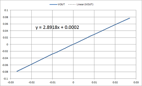
    I plotted gain which is 2.892; that is unexpected and abnormal provided that common mode voltage did not change during the test.

    The zero cross over is very close to zero. Therefore I expect the resistor matching is very good. Same for VIO 

    Are you very sure the resistors ar 24.9k and 10k and not 28.7k and 10k or some other combination?

    Is this a new or old design? What is the issue rate? (for example 15 of 50 do this..)