Other Parts Discussed in Thread: TLC2272
I am using the TLC2272A opamp to detect peak current in a PWM-controlled LED driver.
Typical Operation:
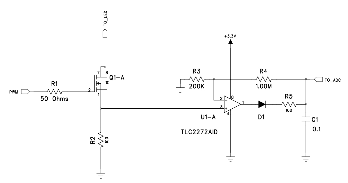
In the schematic below, the PWM control signal is applied to the gate of Q1-A and LED current flows from the positive supply through the LED (connected to node TO_LED) through Q1-A and sense resistor R2 to ground. The circuit must detect LED current at levels as low as 0.3mA, which translates to 30mV across sense resistor R2. U1-A is a peak detector which rapidly charges C1 to 6X the highest level seen on sense resistor R2.
When LED current is removed, Voltage on R2 drops to 0, the output of op-amp U1 drops to 0, and C1 slowly discharges through R4 and the load at the ADC input (1KΩ in series with a 20pf sample and hold capacitor sampling at a 100KHz rate). Software interprets peak detector output below 50mV as an LED-off condition. Leakage in the ADC input is ±1nA - therefore, the ADC input is not supplying a small amount of leakage current to partially charge C1.
The Issue:
At room temperature, in some newly-assembled boards (pick-place/reflow from an assembly house), some peak detectors cannot bring their outputs below 50mV to get the expected “no LED current” indication. Often, a failure will be one or two per board (8 detectors per board) with two failures usually within one pack (these are dual op-amp packs). Usually, replacing the affected pack solves the problem.
Some failures are also seen when the circuit is operated at elevated temperature in an environmental chamber. As above, the failures may happen in pairs within the same IC pack.
Input offset voltage for the TLC2272A is 1.5mV
Any suggestions what may be causing the described problem?


