- Ask a related questionWhat is a related question?A related question is a question created from another question. When the related question is created, it will be automatically linked to the original question.
This thread has been locked.
If you have a related question, please click the "Ask a related question" button in the top right corner. The newly created question will be automatically linked to this question.
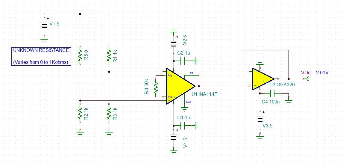
Planning to use INA114 for signal conditioning of a bridge circiut.
Unknown resistance varies from 0 to 1Kohms.
It will be read by ADS1258. Output of the Signal Conditioner has to swing 0 to 5V.
(Please refer the Picture attached)
When the unknown resistance is zero, output of the signal conditioner has to be 5V. But it only gives out put of 2.01V.
The Required gain is 2.
Please help to resolve the issue.
I am trying to interface a wind direction sensor, which has a potentiometer. Its resolution is 0.1 degree (ie. 0.27 ohms/ 0.1 degree).
I have tried with INA326 (as shown below)
When unknown resistance is 0-ohm, it gives out put of 4.75V. (expected is 5V). with 1K unknown resistance, it gives out put of 25mV. (expected is 0V). It is giving offset of ±25mV offset.
Please help as early as possible.
Hello Amarnath,
When R5 becomes 0 ohms the input voltage at Vin+ is set to 5V which violates the input common mode range. This is resulting in the output saturating to 2.01V in simulation. Based off a +/-5V supply and a gain of 2, the Vcm versus Vout calculator shows the highest voltage for Vin+ is 3V.
Best regards,
Errol Leon
Texas Instruments
Precision Op Amp Applications