This thread has been locked.

If you have a related question, please click the "Ask a related question" button in the top right corner. The newly created question will be automatically linked to this question.

TL441: AC component lost after passing logarithmic amplifier

Part Number: TL441
Other Parts Discussed in Thread: TL592B, , TL592

Hi,

I am trying to build a lock-in amplifier. This amplifier needs to operate at 3.58MHz, sine wave. I use TL441 as the logarithmic amplifier, TL592B as the linear amplifier, then the reference signal and the test signal input into the multiplier AD734. Because the tested signal is too low, I have to use two levels of amplifiers. However, after passing through TL441, the AC component in the tested signal was lost. Can any TI Specialist or any friend in E2E community provide any advice on solving this issue? Or TL441 cannot be applied to this range of frequency.

Thank you in advance,

A TI user

  • Hi Jundong,
    Could you provide schematics and sample waveforms from this circuit? That would greatly help in troubleshooting this issue.
  • Hi Alex,

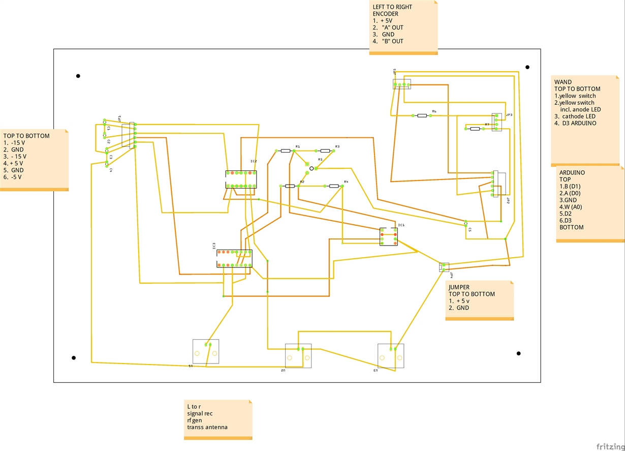
    Sorry for the late reply. I need to check with my advisor to allow me to share our schematics. The chip (IC3) with 16 PIN is TL441. The chip (IC1) with 8 PIN is TL592, and the one (IC2) with 14 PIN is AD734.

    At the bottom of the board are three BNC connectors. "signal rec" means the signal from the receiver. "rf gen" means the signal from the radio frequency generator. "transs antenna" means the connector to the transmission antenna.

    Since checking the whole board did not give me a good result, I checked TL441 separately.
    I checked the points which are supposed to connect to IN+ and IN- of TL592. The signal from the signal generator is at 3.58MHz.
    The signal from the generator is 0.2V (this is the minimum volt we can get from the generator). The voltage measured at PIN4 of TL441 is 78mV (because it is measured by Fluke and Fluke probe has some attenuation). The voltage at IN- is 4.78V (AC+DC), and IN+ is 2.55V(AC+DC). Then I checked AC and DC components separately. I found that IN- is 0.04V (AC) and IN+ is 0.02V (AC), which means the voltage values are mainly from the DC component and the AC component is very small. I checked the frequency and it is not readable.
    Thanks for being willing to help us with the issue of our lock-in amplifier.
    Best regards,
    Jundong
  • Hi Jundong,

    Please repeat your measurements with an oscilloscope, not a handheld DMM. A DMM will not accurately measure AC voltages above a few hundred kilohertz. An oscilloscope will also indicate if there is any unusual clipping, oscillation, distortion, or noise present, which a DMM measurement absolutely will not.

    I sketched out your schematic, and it looks alright. Given that the TL441 and TL592B portion comes from the TL441 datasheet, I wouldn't expect any major issues. One thing that I do find concerning was your measured voltages at the +IN and -IN pins of the TL441. Under normal operation, I'd expect those to be very close to the same voltage. The fact that you're seeing IN+ = 2.55, IN- = 4.78 suggests that something isn't right there. Given those input values, I'd expect IC1 pin 4 to be -4 volts or so. 

    You may also want to tweak your layout a little. While 3.85MHz isn't terribly high frequency, and won't cause layout issues from that perspective, a smaller, more direct layout that minimizes signal loop areas, uses a ground plane, and places power supply capacitors near the devices they're powering should perform better in general, and particularly be less sensitive to noise and external interference.

    These two articles cover some of the basics of layout, although some of the topics they cover won't necessarily apply to your design. 

    http://www.ti.com/lit/an/szza009/szza009.pdf

    http://www.ti.com/lit/ml/slyp167/slyp167.pdf

  • Alex,

    Thank you for your reply and thank you for checking the schematics.

    I used Fluke 190-504/S 500 MHz ScopeMeter® Test Tool which is actually a oscilloscope. You can check the website of this tool: en-us.fluke.com/.../fluke-190-ii-portable-oscilloscope-190-504-s.html. It can be used for high frequency signal and also can show the waveform.

    I get IN+ = 2.55, IN- = 4.78 because I layout TL441 on a breadboard without other chips. It means that I don't have feedback resistor for TL592B and circuit is not symmetric.

    You said that the schematic looks alright, but I don't know why it still not working alright.

    Very appreciate your help.

    Regards,
    Jundong