Because of the holidays, TI E2E™ design support forum responses will be delayed from Dec. 25 through Jan. 2. Thank you for your patience.

This thread has been locked.

If you have a related question, please click the "Ask a related question" button in the top right corner. The newly created question will be automatically linked to this question.

LM258A: Input and Output protection

Part Number: LM258A
Other Parts Discussed in Thread: LM258

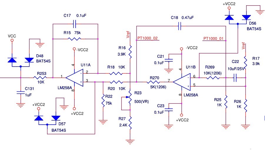
The attached file is my design for PT1000 sensor.  Sometimes , the LM258 will burn out.  I think the cause is the PT1000's fault.  I want to protect the LM258.  The D56 and R269 are used for the input protection of U11B.  The D57 and R20 are used for the input protection of U11A.  The R270 is used for the output protection of U11B.  Can you give some advice?  When the output of the LM258 suffer a high voltage(may be Vcc), how much is the limit current?


Thank you very much.

Best regard.

Jiunhung

  • Jiunhung,

    What is the symptom when LM258 goes bad? Do you know what pins are affected?
    Do you have a link to the PT1000 sensor.
  • Dear Ron,

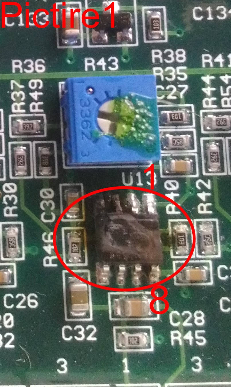
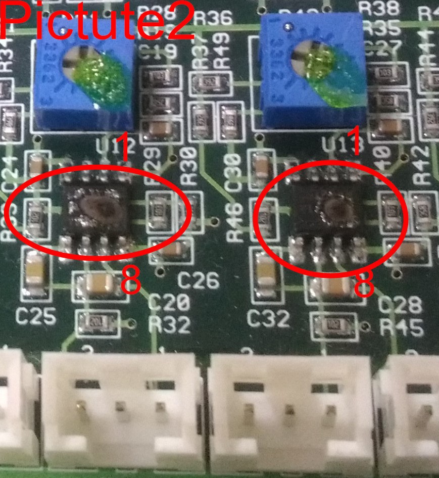
    I have two failed examples. In the picture 1 ,the pin 3 &4 and the casing of the LM258 are burning and the pin 7 is some burning.  In the picture 2, the casing of two LM258 are burning, but pins are ok.

    The Pt1000 sensor is a resistance thermometer. I connect it to the  pt1000_01 and pt1000_02 in my circuit. The pt1000 can refer to en.wikipedia.org/.../Resistance_thermometer.

    Thank you for your help.

    Best Regards.

    Jiunhung

  • Jiunhung,

    Looking at the board, I assume that the protection items mentioned are for a future board design and currently not implemented on the board.

    The damage is impressive which suggest that somehow there became an internal short (high current leakage, not zero ohms) from pin 8 to pin4. Very high VCC well over 40V could do that. Because both devices failed, I suspect VCC2+/VCC2- bus stress.

    The PT1000 heat sensing resistors appear to connect via the white connectors. Connectors often are an entry point for ESD, however,I would not expect burn damage from a human ESD event at the connector. Do the remote PT1000 resistors touch or are close proximity to high voltage nodes or electrical nodes that have different ground point?

    Do these EOS failures occur in factory or in the field? Do other components on the board also suffer damage?
  • Dear Ron,

    Thank you for your response.

    1. The circuit that I posted is a new design, not yet implemented.

    2. There are five PT1000 channels in my PCB.  In the picture 2, two LM258s are damaged but another three LM258s are OK.  So, I think that +VCC2 and -VCC2 are OK.  You can see the new picture below.  

    3. The PT1000s are mounted on the casing of my machine that include two motors and one inverter.  The machine are our product and the failure events happened in my factory.  I think that there are some noise or some induce current in the wires of PT1000 sometimes.  On one occasion, I find the one wire of PT1000 is connected to the shielding ground.  Although some faults come from the PT1000,  but I would to do something to protect my LM258.

    4. Can you give me some advice for my new design?  Is the R270 for the output protect suitable? 

    Thank you.

    Best regards.

    Jiunhung

  • Jiunhung,

    The new design will definitely improve the tolerance to external stress. R270 value is good. Is one of the pins on the connector ground?