Because of the Thanksgiving holiday in the U.S., TI E2E™ design support forum responses may be delayed from November 25 through December 2. Thank you for your patience.

This thread has been locked.

If you have a related question, please click the "Ask a related question" button in the top right corner. The newly created question will be automatically linked to this question.

THS4032: Single Ended Multiple Feedback Amplifier Design

Part Number: THS4032
Other Parts Discussed in Thread: OPA2209

I am in the process of designing Single Ended Multiple Feedback amplifier for band pass filter. The center frequency of the 4th order band pass filter is 1MHz (should operate between 500KHz and 1.5MHz). I had designed using filterpro software and referred some other application notes like "SBOA114".

The circuit schematic generated from filterpro software is different from the schematics as given in the Figure 1 of "SBOA114".

I have tried both the circuit schematics (from filterpro as well as "SBOA114") but am unable to get the gain of 0dB (I am getting gain of -6.97dB max). Can someone guide me as to how I can increase the output gain by changing the passives in the circuit? I am currently using OPA2209 in the 4th order band pass filter.

  • Hi,

    Can you share your current schematic that you are using?

    Regards,
  • Hi Jacob,

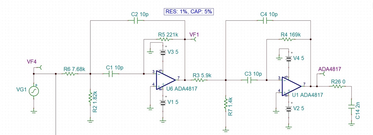
    Sending the schematics as attachment. I have done some more experiments with this circuit till today.

    I have found out that to increase the gain I only have to vary the resistance values of R6 and R2 for 1st filter and R3 and R7 for the 2nd filter. But still for some resistance values I find that the harmonics increase to large extent (till -30 to -40dB when the fundamental frequency is at 0dB). I would like to know what parameter of the Operational Amplifier do I have to consider to select the resistance values such as to educe the harmonic content from the Operational Amplifier.

  • Abhijit Pethkar,

    You are designing a 4th order bandpass filter. With this filter you have two high-pass filters followed by two low-pass filters. Because of the bandwidth of your filter, the high-pass filters (3dB @ 500kHz) have not completed reached the final gain value before the low-frequency corner or the low-pass filters (3dB @ 1.5 MHz)  start to attenuate your signal bandwidth prior to the theoretical high frequency corner. For both of these filter pairs, by definition the 3dB frequencies are producing an attenuation to the circuit gain at those freuqencies. To corect this problem, design your circuit with a gain of something like 7dB. Please note, your circuit is not "broken", it is actually operating exactly like it was designed to do.   

  • Hi Bonnie,

    Thank you for the help. After I increased the gain, I am able to use the filter with less harmonics.

  • My pleasure. I am glad that this was an easy fix.

    In the future, you may want to consider using TI's Filter Designer (www.ti.com/.../webench-filters.html).

    This software will give you recommended devices for your filter, the simulation results, and recommened resistors and capacitors. It will also allow you to switch between Sallen-Key and MFB filters. The software will give you a BOM if you are intested. The simulation results include AC gain and phase, step response, sine wave response, group delay and noise. Simulations are performed with TI Spice and uses the device's macromodel.

    I think that you will find that you will see much more information that this site will provide. For your information, Filter Pro software is the backbone of this site so you will not see any discrepancies.

    Have fun with this software. It is a good design tool.