A related question is a question created from another question. When the related question is created, it will be automatically linked to the original question.
If you have a related question, please click the "Ask a related question" button in the top right corner. The newly created question will be automatically linked to this question.
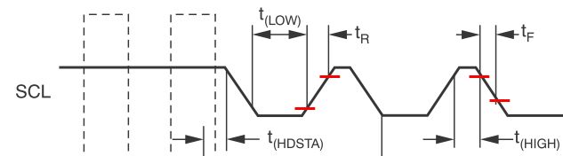
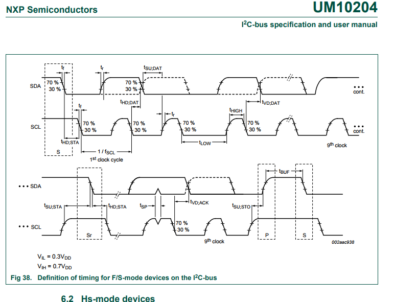
We specify our rise and fall times using the standard 30%/70% marks of the full-scale signal. This is the same standard as the UM10204 specification. So if our I2C characterization of the INA231 was with a 5V full-scale signal, then we measured rise and fall times on the INA231 SCL and SDA lines as the times from 1.5V to 3.5V.
Hope this help,
Peter Iliya
Current Sensing Applications
Let me ask more about VIL and VIH of SCL/SDA.
The VIL and VIH should be 0.99V and 2.31V at VDD=3.3V if it refer UM10204 specification. However the VIL and VIH in electrical characteristics is specified as 0.4V(max) and 1.4V(min). I think this should be VDDx30% and VDDx70%, is my understanding correct?
There is a difference between how we measure rise and fall time versus how specify VIL/VIH.
We measure rise/fall times based upon the 30% to 70% level of the full-scale signal.
We specify VIL ("input-low") and VIH ("input-high") as the input specifications. If the master wants to communicate with our device, it must have a LOW digital logic level that is inside our VIL range (-0.5V to 0.4V) and it must have a HIGH digital logic level inside our VIH range (1.4V to 6V). We create these ranges so that no matter how the INA231 (or most of our digital current-sensing devices) is powered, the master can communicate with the device even if master device is operating on 1.8V, 3.3V, or 5V logic levels.
The VOL ("output low") is an output specification of our device. This specifies what our device considers as a LOW digital logic level when it is transmitting data out to the master.
I hope this helps.
Sincerely,
Peter Iliya
Current Sensing Applications