Other Parts Discussed in Thread: TINA-TI, , PGA205
Hello,
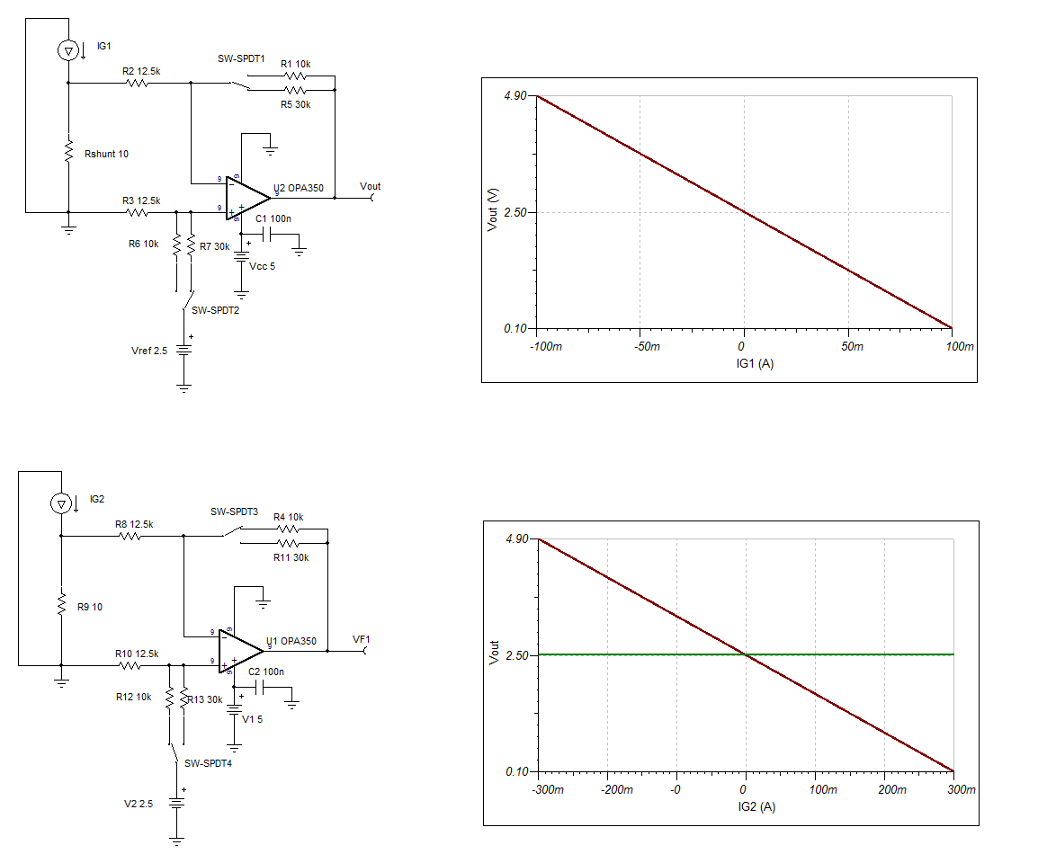
We’re driving a current sensor that has a current source output. We will be using a range of current sensors with an output range from about +/-100mA to about +/-300mA. This measured current to a microcontroller ADC. The circuit needs to be configurable so that we can adjust the scaling based on which current sensor is in use. The general topology for this will be a current sense resistor followed by a diff-amp. ( I can share schematic offline.)
The first idea we had for configurable scaling was to use a fixed diff-amp gain and implement selectable sense resistors. The drawing below shows up to 5 selectable sense resistors.
Note:
(1) The sense resistors are in the less than 10Ω range so the switch needs to have very small ON resistance. (seems like 10mOhm is a good value for negligible error)
(2) Looks like there will be current swings positive and negative, so does the voltage across the sense resistor. This means that the switches that are opening up the unused paths must be able to block bipolar voltages. A single MOSFET won’t work because the body diode will conduct during the negative side of the cycle.
The other option was to use a single, one-size-fits-all current sense resistor followed by a variable gain amplifier.
Would you recommend one or the other implementation?
Or have an alternative solution?
Thanks very much, Keith


