This thread has been locked.
If you have a related question, please click the "Ask a related question" button in the top right corner. The newly created question will be automatically linked to this question.
Dear Sirs
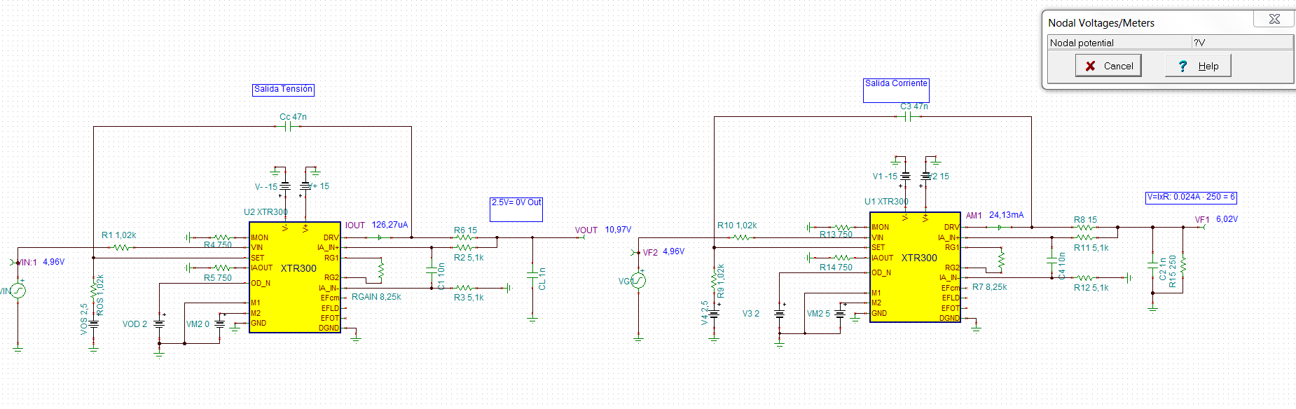
Our Incoming XTR300 Based Design Will Output +-10V Or +-24mA (Depending on M2 State)
Design Its Based On tiduah1 www.ti.com/.../tiduah1.pdf
For Current Output, Simulation Works Fine, and I understand the formula
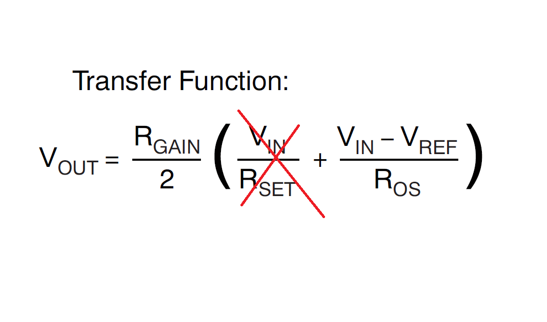
But For Voltage Output, the red marked formula seems to be wrong
Ignoring the red marked formula and usng the blue marked formula, simulation is not precise at all, also when solving For VDAC=2.5, blue equation fails (VDAC-VREF=0)
What is the correct output expression ? I mean: Vout=........
I´ve tried to look at datasheet but datasheet equation expects ROS and RSET, i have only 1 of them
NOTE: For IOUT, i placed 250R to observe the output current
Probably Vout Expression is:
Vout= ( (VDAC-2.5) / 1020 ) x (RG/2)
Vout= ( (VDAC-2.5) / 1020 ) x (4125)
PD: Similar to the Currrent Expression
Iout= ( (VDAC-2.5) / 1020 ) x 10
Hi Ignacio,
You are right, the red equation (or equation 5 in the TI design) is not correct and R65 was left out. The correct expression for Vout would be (Rgain/2) *(Vdac - Vref)/Rset. Unfortunately there are some problems with the XTR300 model when operating in voltage out mode. It does not always produce accurate answers but if you follow the datasheet guidelines then your design will function as intended. I apologize for the inconvenience, I am hoping to get this model updated in the near future to resolve these issues.
Solving the blue equation presumes you are selecting R65 to set the desired full scale output voltage. It wouldn't make sense to set this point at Vdac = Vref because this implies a net 0V input, and the output will be 0V regardless of the value of R65.
Dear Sir
You equationVout= (Rgain/2) *(Vdac - Vref)/Rset its the same as i purposed
Gives for vdac 4.96 : (4125*2.46) / 1020 : 9.94, Fine!
Please tell me what can i do with the schematic for achieving precise results for bipolar voltaje output?
What is the problem, when bipolar out only?
I´ve selected XTR300 for having an all in one solution and i dont want to design a new stage only for Voltage out...
Kind regards
Hi Ignacio,
I'm not quite sure what you are asking. The simulation is not going to reflect the true accuracy of the XTR300 in voltage output mode. The true output should be closer to that predicted by the equations than what is shown in sim. The dominant error sources in this design are going to be your gain setting resistors (which you can adjust by using higher precision resistors), the gain error of the internal op-amps, and the offset voltages of the internal op-amps. If you want an estimate of the error you will see in voltage and current output modes, then you can use the attached spreadsheet to approximate this.
Ok so i can perform real tests ( low scale, zero, and full scale) -10, 0, +10
Measure results
And apply a FW correction constant?
Kind Regards
Its necessary to redesign the boards for XTR111 ?
Kan I keep Using the XTR300?
What´s your suggestion
:(