This thread has been locked.

If you have a related question, please click the "Ask a related question" button in the top right corner. The newly created question will be automatically linked to this question.

TINA/Spice/OPA657: Very Basic Query regarding Phase Margin/Stability

Part Number: OPA657
Other Parts Discussed in Thread: TINA-TI, TLV3501

Tool/software: TINA-TI or Spice Models

Hi Folks,

I am very new to the analogue world (have spent 40+ years in the digital world !) so please be gentle if what I am about to ask is just nonsense !

I attach a Tina-Ti example file for a 100Hhz Transimpedance amplifier that I have run an AC Analysis on and embedded the Gain/Phase Plot I get. 

From a stability point of view I am being told that the phase margin is the difference between the phase at 0dB gain and -180 degrees. The plot shows the phase going from 0 to over 360 before

the gain reaches 0dB. Also I assume that as the phase approaches -180 just as the gain begins to roll-off that this would be a point of instability ?

In essence .... do these curves not prove that this circuit  is inherently unstable ?

100MHz Photodiode Amplifier Query.TSC

3414.100MHz Photodiode Amplifier Query.TSC

  • Hi Iain,

    Your understanding of the stability criteria is correct, but for stability you need to be able to look at the loop gain of the circuit, which is the Aol response of the amplifier times the feedback factor created by the feedback network. The TI Precision Labs chapter on Op-Amps has some very good information on stability including how to simulate using TINA.

    TI Precision Labs

    I ran your circuit in a stability setup and it looks like you should be okay with a phase margin of about 35 degrees. 

    Regards, 

    100MHz Photodiode Amplifier Query Stability.TSC

  • Hi Jacob,

    Thank you for your reply, I can see now how this should be done.

    However can I ask why and what are the extra capacitors C6 = 700f and C7 = 4.5p ?

    Regards

    Iain Wilkie

  • Hi Iain,

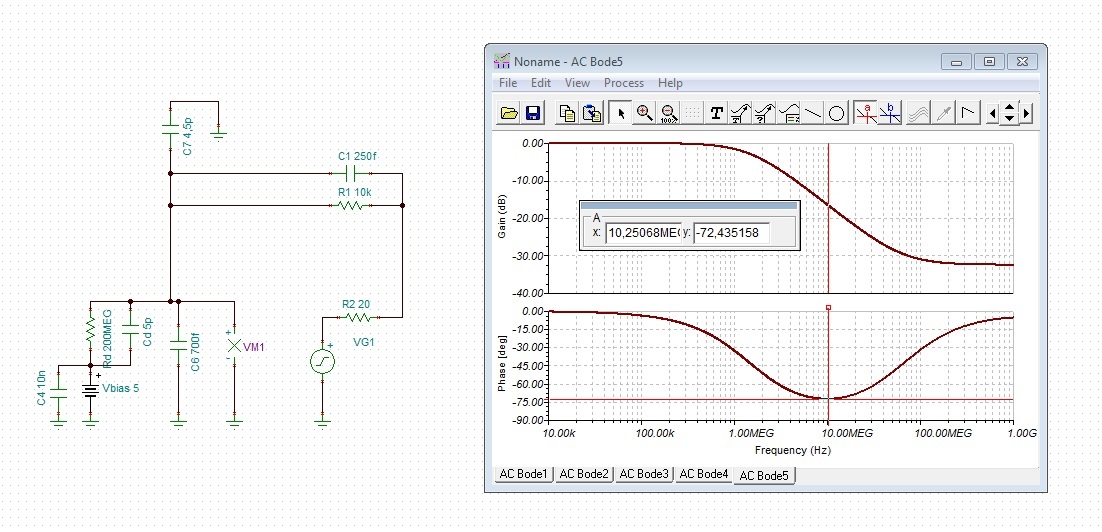
    a simplified phase analysis which only takes into consideration the open loop output impedance of the OPAmp could look like that:

    I have also added C6 and C7, like Jacob already. These are the input capacitances of OPAmp which have also be taken into calculation.

    The simulation shows only the additional phase introcuded by the feedback loop.The phase shown in the simulation has to be added to the phase curve in figure 16 of datasheet.

    There's a critical phase minimum in the simulation at about 10MHz. The phase margin of the whole circuit can be estimated to 180° - 90° - 72° = 18°. This a very small phase margin. You should have at least 30°. But that's my personal taste...

    Kai

  • So as I understand the input capacitance is not part of the opamp spice model and needs to be added manually ?

    Also I am a bit confused as I have seen in this opamps datasheet a circuit where it is used as a transimpedance amplifier with a gain of 200K (106dB) but the datasheet indicates an open loop gain much lower that this, how can that be ?

    Not sure if I am asking stupid questions here but I do appreciate your help and comments.

    Iain
  • Hi Iain,

    "transimpedance gain" is not a gain in the usual sense. It's not "output voltage" divided by "input voltage", but "output voltage" divided by "input current". In this TIA design it is "output voltage" divided by "photodiode current", which is just the feedback impedance of the transimpedance amplifier, because the -input is on virtual ground.

    In the datasheet on page 1 you see a TIA with a feedback resistance of 200k. This means a "transimpedance gain" of 200k, which is 106dB. In your circuit you have a feedback resistance of 10k. So, the "transimpedance gain" is 10k, which 80dB. By the way, the "transimpedance gain" has nothing to do with the "open loop gain" of the OPAmp. The first is something of the whole circuit, including the feedback components, and the latter has only to do with the OPAmp itself. It's a true gain and is the "output voltage" divided by the "input voltage" being applied between the + and - input terminals of OPAmp.

    In the stability analysis the "gain" can again have a different meaning. In my simulation the "gain" is the dampening factor within the feedback loop. This has nothing to do with the "transimpedance gain". It's only an auxiliary parameter helping to estimate the stability of the circuit.

    The input capacitances are not always included in the Spice models. But even if they are, it can be helpful to add them externally. This will double the input capacitance and create a sort of worst case condition, as the input capacitance shows production tolerances or can be influenced by stray capacitances of the layout.

    Kai

  • Kai,

    Thank you so much for your detailed explanation and taking time to reply.

    This gives me a much better understanding.

    As mentioned in my first post I am a digital engineer so this is a bit of a diversion for me into the analogue world.

    The feedback you guys are giving is very helpful and much appreciated.

    My completed circuit contains two OPA 657 opamps, the first being a transimpedance amp with a gain of x100k followed by the second which is ac coupled and has a gain of around x20. The output of this second opamp feeds a comparator.

    If it was ok, it would be great if you could review the circuit just to see if there are any major or hidden problems. I have been using Tina V11 and realise

    that this cannot be read by the current V9 of TINA-TI so unless you guys are using V11 I will need to recreate in current TINA-TI, but that’s no problem.

    The PCB layout has been completed for this design, I am seasoned PCB designer and am aware of the requirements there (I.e. stray capacitance etc) so I am not concerned about that aspect, in fact it’s being fabricated right now !

    If you can help with a quick review please let me know if you can handle the .tsc file in TINA-TI or Tina V11 and I can post it.

    Thanks again for all your help.

    Regards

    Iain

  • Guys,

    I have re-created the circuit in TINA-TI and attached it here.  Hope someone will be good enough to look at this and feedback any mistakes !!!

    IR Reciever TINATI.TSC

  • Hi Iain,

    I see an issue: You have a single pulse chosen for the photodiode current signal. If you would have chosen a periodic signal (general waveform) you would have noticed, that at the +input of U2 an AC voltage arrives which not only goes positive but also negative. This is the consequence of RC filter C3/R5. How much the + input goes negative depends on the duty cycle of your photodiode current signal. As consequence the input of comparator U3 also sees a negative going AC input voltage, which is troublesome, because it's powered by a +5V single supply.

    You wrote that the pulses come from the photodiode with a maximum repitition rate of 1MHz. Is there also a minimum repetition rate? I ask, because eventually the highpass filter C3/R5 can be improved and be adapted to the actual repetition rate. In fundamental partice detection applications this is usually done. It's called "shaping".

    Kai
  • Kia,

    Thank you for looking at this and your swift reply !

    All I can tell you about the PD current is that there is always a standing current of about 6uA which then dips by about 150nA for 100nS. This can happen repetitively but no faster than 1uS ..... however will normally be much less even a few hertz.
    I do understand your observations however my main concern in all this is stability, I'm hoping for a working circuit and not an oscillator !!

    Regards

    Iain
  • Hi Iain,

    I will again have a look at it, when I have time...

    Kai
  • Hi Iain,

    the application is critical! I would choose C2=200f, C5=300f and R6=220R. Even the low input capacitance of TLV3501 has an impact on stability.

    Let's see what Jacob says to all this.

    Kai
  • Hi Kai,

    Thanks for looking at this and your suggestions. All this stability stuff is pretty alien to me but I am learning !!
    I do appreciate you spending your precious time and expertise with me.
    I will await the arrival of the PCB and get this built up and tested, and post the outcome.

    Regards

    Iain
  • Hi again Guys ...

    I have just been through training.ti.com/ti-precision-labs-op-amps-stability-3 where the 1T inductor to open the feedback loop is placed between the output of the amp and the feedback, and the 1F capacitor and generator is placed at the junction of the inductor and the feedback loop. This is different from what Jacob has done above and indeed gives completely different results.
    What determines how these elements should be placed for this type of analysis ?

    Regards

    Iain
  • Hi Iain,

    there are many ways to do these simulations. I have no time to analyze the results of the many ways, but I can say, that my simplified phase analysis and Jocob's simulation both showed the dangerous phase minimum at 10MHz. Jacob found 17.2° phase margin and my simulation gave a phase margin of 18°. This is a close match. So, Jacob's simulation cannot be totally wrong.

    Kai

  • Hi Guys,

    Sorry, I wasn’t saying Jacobs sim was different from yours Kai, it was  just that after going through the TI training on this as suggested by Jacob, I realised that their method was slightly different and when I applied to the original transimpedance circuit the results were totally different which

    I was finding a bit confusing.

    I am quite happy to be guided by your expertise, you have the experience and I appreciate the help. To a digital engineer this is all very new ground but I find it very interesting .

    I do have a lot to learn !

    Cheers

    Iain

  • Hi again Guys,

    Ok I am now beginning to see the light !! looking at both Jacobs and Kai's methods of determining the phase angle margin.

    I have one last query (i promise !) ... In Jacobs method he indicates the phase angle as 35 degrees at 0dB point .... but Kai

    uses the minimum18 degrees at which is at 10M as the phase value (also seen on Jacobs). So the question is which one of these would you use

    to determine the phase margin for stabilty ?  I note in the literature it seems to indicate that this be measured at 0dB as per Jacobs 

    simulation, but to me it seems obvious that if the phase margin was closer to -180 degrees before the 0dB point (as per Kai's) then

    this would be the major point of instability. Am I correct ???

    Also Kai, I note you have used an output resistance of 20R in your simulation, can I ask where this comes from ?

    Cheers

    Iain

  • Hi Iain,

    Jacob's simulation takes into account the behaviour of the feedback loop AND the OPAmp. My simplified simulation only shows the behaviour of the feedback loop. The only characteristic of the OPAmp I have taken into my simplified simulation is the open loop output impedance, which I estimate from figure 26 of datasheet to 20R and the input capacitances. So, looking at my simplified simulation tells only half the truth. You must still add the phase shift of my simulation to the phase response of figure 16 of datasheet. Jacob gets 35° phase margin at about 80MHz (0dB). This is nearly the same what I get, if I add my phase to the phase of figure 16 of datasheet: 180° - 35° (of my simulation) - 110° (from figure 16) = 35°. This is also 35° phase margin, or by other words, 35° more positive than -180°.

    Dangerous is every region where the phase shift comes close -180°. In your application this is the region from 10MHz to 80MHz. Beyond 80MHz is not so critical, because the total gain in the feedback loop is <1 and oscillation can no longer occur.

    The reason why I use this simplified simulation is because when I learned this stuff TINA-TI didn't exist. And the Spice models being available at that time weren't very trustworthy. But, of course, today you should use the method Jacob is showing us...

    Kai

  • Kai,

    This is all making sense to me now !! .... Again thanks for your perseverance in assisting me with this.

    So basically as I understand things now if the total phase shift around the loop approaches say 150 degrees) or greater (i.e.30 degree margin or less) at  any point in the frequency spread up to where the gain becomes less than 1, then there could be stability problems causing the circuit to oscillate.

    I now feel confident in assessing this now.

    Again, many thanks for your help 

    Cheers

    Iain