Because of the holidays, TI E2E™ design support forum responses will be delayed from Dec. 25 through Jan. 2. Thank you for your patience.

This thread has been locked.

If you have a related question, please click the "Ask a related question" button in the top right corner. The newly created question will be automatically linked to this question.

LM7171: Inductive load

Part Number: LM7171

Hi,

I am generating a signal at 10MHz which will drive an inductive load requiring about 80mA p-p. I am using LM7171 as a buffer. Simulation does show that LM7171 can drive the load but I am skeptical that the practical circuit will behave the same since the datasheet never mentioned inductive load. Can anyone advise on an amplifier that can drive an inductive load at that frequency?

Thank you 

  • Hi Raymond,

    can you show us a schematic?

    Kai
  •  Hi Kai,

    Thanks for your response. It is a basic voltage follower circuit. I have attached it.

  • Hi Oro,

    an inductive load at the output of an OPAmp can be problematic for two reasons: It can present a short circuit at low frequencies where the impedance of the inductance is not yet coming to play. Or the interwinding capacitance can present a too high capacitive load to the output of OPAmp. Because of this in many cases a resistance is put in series to the inductance to increase the impedance at low frequencies. Another way to handle the low frequency short circuit of inductive load is to drive the inductive load by a current source instead of a voltage source.

    Do you have any information about the series resistance and interwinding capacitance of your 2µH inductive load? Can you tell more about your application?

    Kai
  • Hi Oro,

    Though your system is running at 10MHz, Kai is correct that you should consider putting a series resistor to the output. I also ran your circuit through some TINA simulations and noticed you are getting some ringing at the crossover. The series resistor should help minimize that effect as well.

    Regards,

    Robert

  • Hi Robert,

    Thanks for your response. Is there need for a resistor even when you are connecting the coil via a BNC that has 50ohm impedance? If I still need a resistor, what value is most appropriate?

    Regards,

    Oro

  • Hi Oro,

    Just so I understand, you are saying that you have a BNC with a 50ohm impedance that is connecting the output of the LM7171 to the coil?  Thus it looks like a 50ohm impedance is in series with the inductor.


    Regards,

    Robert

  • Hi Robert,

    I intend to put a BNC of 50ohm at the output of LM7171.

    Thanks,
    Oro
  • Hi Oro,

    A BNC usually has a characteristic impedance of 50-ohms or 75-ohms, given by Zo = sqrt(L/C) at high frequencies. At DC, the impedance of the BNC cable is still very close to 0- ohms, if you assume the BNC cable using a distributed RLC model. So, you would still need to add some external resistance to the BNC cable close to the LM7171 device. I think a 2 to 5-ohm should help limit the output current from the device.

    If you look at Table 6.1 Absolute Max Rating, the device can do continuous output short circuit to ground/supply at ambient room-temperature (foot-note 3). So, it is possible that you can directly drive the output into the inductive load. However, I would certainly have a placeholder for 2 to 5-ohm resistor just in case, and also would not recommend elevating the ambient room temperature (or essentially exceed the max junction temperature beyond 150'C).

    Best Regards,

    Rohit


  • Hi Rohit,

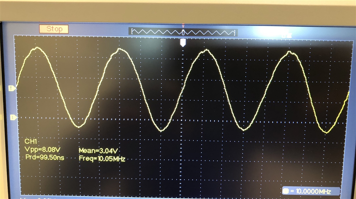
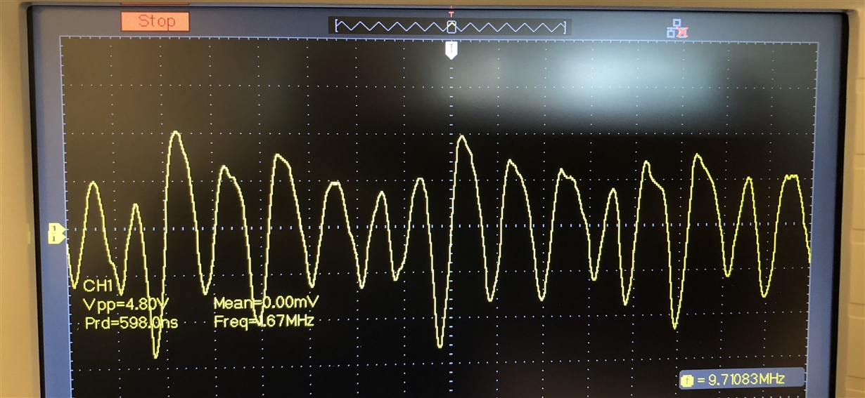
    Thanks for your response. I have built the circuit, please see attached the waveform without load and with load.

    Thanks,

    Oro

  • Hi Oro,

    I guess you circuit suffers from too much load capacitance and oscillates at 100...150MHz. What you see at the scope could be a sort of aliasing artifacts.

    May I repeat my queation: How much interwinding capacitance has your 2µH load?

    How long is the cable to the 2µH load? Or by other words, what cable capacitance are we talking about?

    Kai
  • Hi Kai,

    I have no idea of the interwinding capacitance. The load is connected directly to the output of the amp via a 50ohm BNC. Note that a 5ohm resistor is placed before the output of the amp

    Thanks
    Oro

  • Hi Oro,

    what is the load? Can you tell more about it? Can you show a picture?

    I would increase the 5R isolation resistor a bit, up to 50R. Also, I would shield the magnetic field of the inductive load from the input lines a bit. Or introduce a small distance between the load and the input lines.

    Do you have proper decoupling caps at the LM7171?

    Kai