Because of the Thanksgiving holiday in the U.S., TI E2E™ design support forum responses may be delayed from November 25 through December 2. Thank you for your patience.

This thread has been locked.

If you have a related question, please click the "Ask a related question" button in the top right corner. The newly created question will be automatically linked to this question.

TLV342: TLV342IRUGR Output Current Capability

Part Number: TLV342

Hi, I'm looking for an op-amp to buffer a signal and provide an output of 2 -> 5V to a load of 100 - 200R. This would require driving the load with 50 - 100 mA. The TLV342IRUGR has a specified output source current of 115 mA, but I'm not sure if this just means an absolute max or a max where the output voltage signal will be maintained? Will the voltage output have degraded substantially at roughly this current? If so, what are my options for op-amps capable of driving 50-100mA over 2-5V without significant degradation?

Many Thanks,

Dave

  • Hi David,

    you mean the output short circuit current specification of 113mA typical and 60mA minimum at 25°C? This is not an output current the TLV342 can deliver during normal operation. Like the name says the ouptut is short-circuited to GND in this moment, or by other words, the output voltage is 0V.

    See also figure 6 of datasheet. With a supply voltage of 5V the TLV342 can output a voltage of 4V when sourcing 40mA. Keep also in mind, that this value can have some production tolerances.

    Can you tell more about your application? The output of OPAmp could eventually be made stronger by using a transistor buffer at output.

    Kai
  • Hi David,

    Kai is correct with his description of the short circuit current. Add the additional point that the TLV342 will be operating in a strongly non-linear fashion for high current output as well. Kai's suggestion of using an op-amp to control a transistor which is capable of driving more current is a good one.

    For a strictly op-amp based solution, I recommend looking at TI's Power Op Amp portfolio: www.ti.com/.../products.html

    I'd be happy to assist you further if you want to share a little more about your design and requirements.

    Best,
    Paul
  • Thanks Paul, thanks Kai.

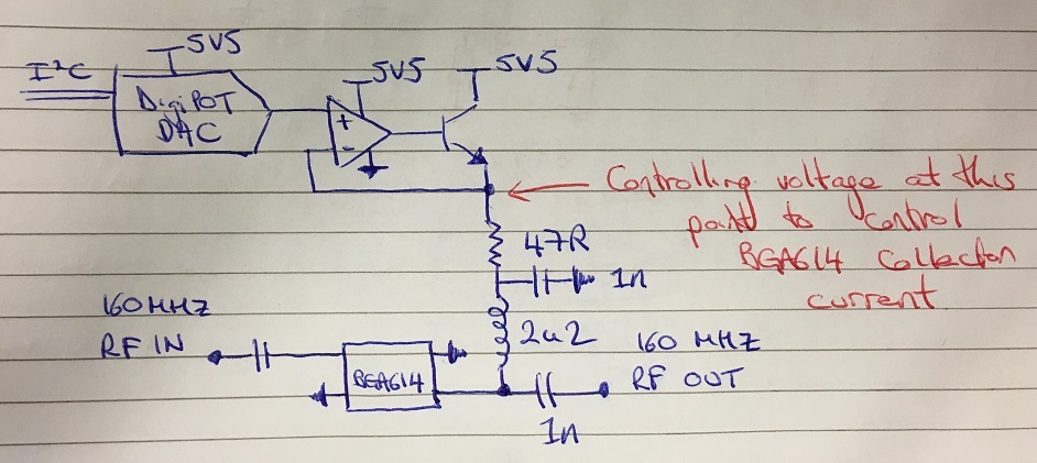
    I'm trying to control Infineon's BGA614 RF Amplifier by varying the Collector voltage through a DigiPot. Since the amp will draw up to 50mA I will need to buffer the DigiPot output. The range of voltages I am looking for is ~2-5V, and I need to be able to deliver whatever the amplifier needs over this voltage range (somewhere between 10 - 50mA usually).

    My application is in a 160 MHz RX path so I'm keen to minimise noise as much as possible. I like the BJT output buffer idea but I'd need a low noise package to ensure I'm not injecting noise into the RF path.

    Does this sound reasonable?

    Cheers,

    Dave

  • Hi Dave,

    I'm not quite following - would you be able to sketch up a quick schematic for me to look at? Are you trying to control the gain of the BGA614?

    Thanks,
    Paul
  • Thanks Paul, please see attached rough sketch. Yeah that's right, trying to control the gain of the BGA614 - it's pretty non-linear but some gain control would be useful. Was thinking of using something like the BFP620FH7764XTSA1 from Infineon for the BJT due to the low noise.

    Many Thanks,

    Dave

  • Hi Dave,

    I think what you are proposing makes sense. The requirements on the op-amp will be low as far as current output, allowing you to stay within the linear operating region for low distortion. Your choice of amp will depend on how fast your dig-pot input is changing as well as how much current you want to dissipate and other system parameters.

    Take a look at this TI Design which provides an example on how this is done: http://www.ti.com/tool/TIPD146

    Best,
    Paul
  • Many thanks Paul, that app note was very useful wrt choosing the BJT. I have two more quick general questions regarding that circuit, then I'll leave you alone!

    Would it make more sense to use a FET in place of the BJT due to my low noise injection requirements?

    Is there any issue with putting 2x BJTs in parallel at the Op-amp output?

    Many Thanks,

    Dave

  • Hi Dave,

    As far as the noise is concerned, I would think that a BJT would be a better choice here because the output of the op amp is generally low impedance and BJT's have lower voltage noise for a given Iq than a FET does. BJT in this particular application might also be additionally helpful for stability as it doesn't have the same type of input capacitance issue that a FET will. 

    This app note doesn't discuss your circuit topology, but it does discuss BJT and CMOS noise in a good way, you may find it a useful read: http://www.ti.com/lit/an/slyt470/slyt470.pdf

    With the BJTs in parallel, what are you thinking you'd accomplish doing that? The main concern I would see is making sure that the op-amp has sufficient drive current for both BJTs. If you're looking for more gain and lower op-amp drive current, you may consider using a Darlington pair to get higher hFE from the transistors.

    Best,

    Paul

  • Great, many thanks for your detailed replies Paul. I'll prototype the circuit and see how we get on!

    Cheers,

    Dave