This thread has been locked.

If you have a related question, please click the "Ask a related question" button in the top right corner. The newly created question will be automatically linked to this question.

OPA192: Cross-Over Frequency Calculation.

Part Number: OPA192
Other Parts Discussed in Thread: OPA172

Hello Team,

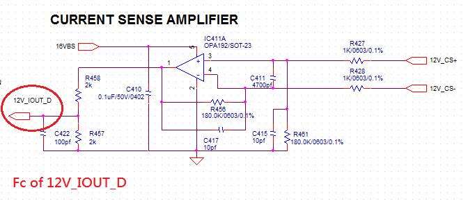
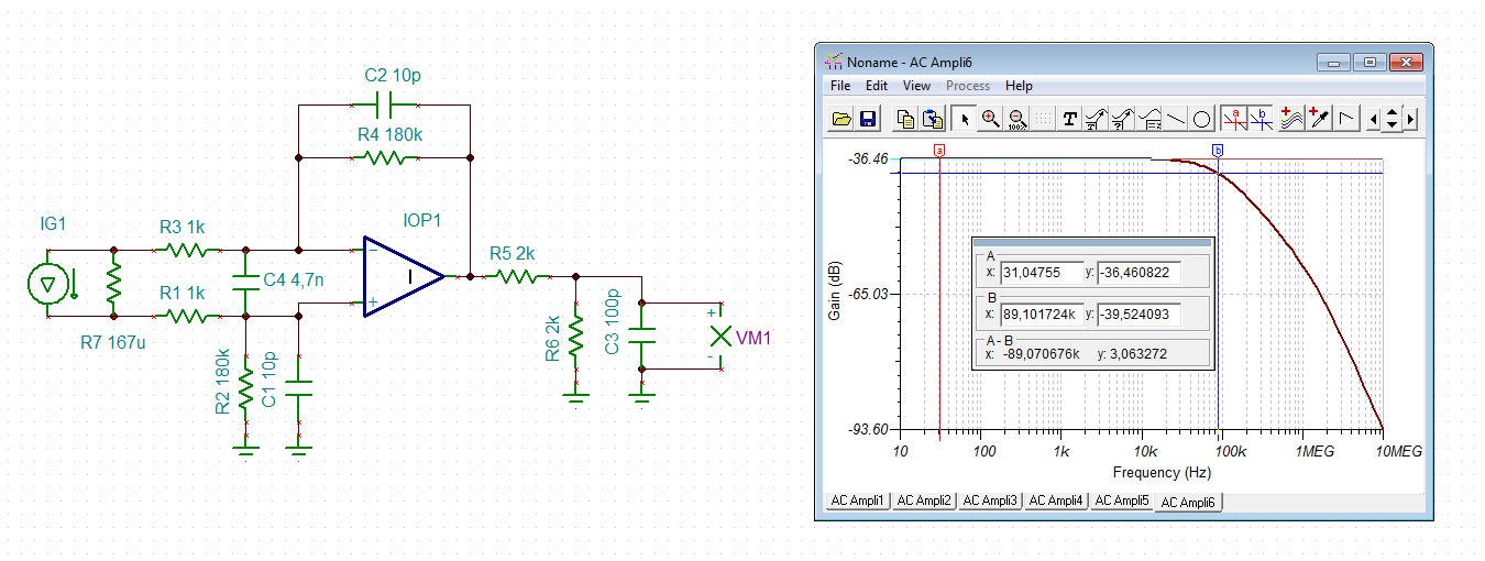
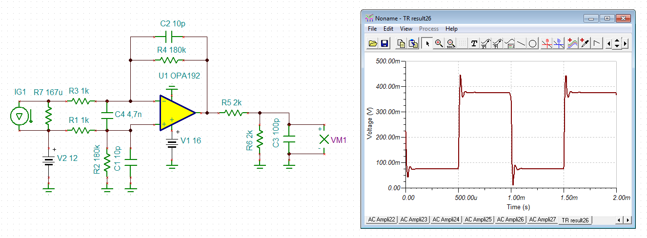
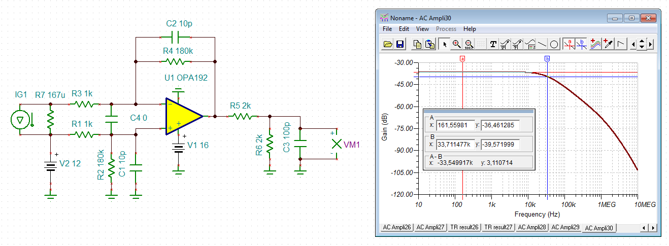
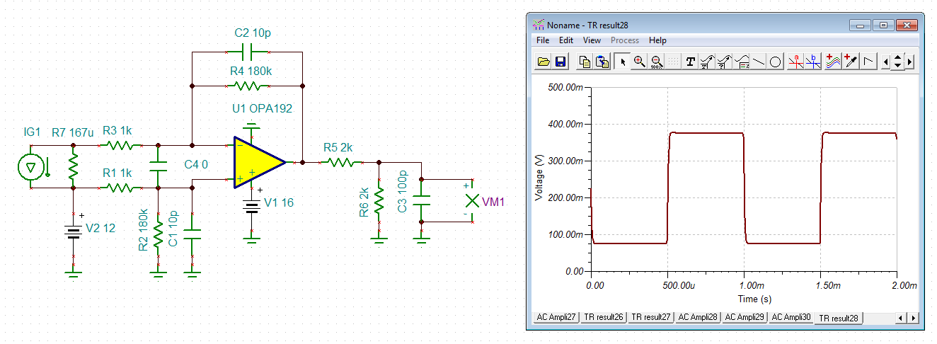
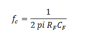
My customer is using OPA192 as current sense amplifier, the CS resistor is 0.167mohm, based on the schematic they have, how's the the cross over frequency looks like? and how to calculate? because the CS resistor is too small, it's hard to do real test, can you tell how to calculate the fco?

Thanks.

Martin

  • Hi Martin,

    low pass corner frequency is about 90kHz:

    Take care, C411 can make the OPA192 unstable! I would remove it.

    Kai

  • Hello Kai,

    As you mentioned C411 can make unstable, why you have C4 4.7nF? did you come out the loop gain graph by C4? can you tell why?

    If remove C411 is recommended, then can they put 4.7nF cap on input (+/-) to gnd to filter ripple and noise? If they can, how does it impact fco? can you help come out the loop gain with bypass cap 4.7nF on input (+/-) to gnd?

    Thanks.

    Martin

  • Hi Martin,

    in the simulation an ideal OPAmp was used. Just for the simulation of the frequency response due to the low pass filters. It does not show the real performance of OPA192!

    If I have time I will simulate the OPA192...

    Kai

  • Hi Martin,

    what is connected in series to the shunt resistance?

    Kai
  • Hi Kai,
    It's OK I understand the simulation just an ideal OPAmp is used, not a problem. they just want to see how fco change if add input RC filter.
    Customer hopes to get answer sooner, please help come out the simulation by today,
    Thanks.
    Martin
  • Hi Kai,
    As I mentioned in first post, the CS resistor is 0.167 m-ohm.

    Martin
  • Hi Martin,

    in the following you will see the frequency response and the transient response of your circuit:

    It was current signal through the shunt simulated of 15ADC, superimposed by a 1kHz square wave of 10A amplitude. The corner frequency of low pass filtering is about 40kHz. The frequency response shows a resonance and the transient response shows a heavy ringing.

    Omitting C4=4n7 yields the following simulations:

    Corner frequency of low pass filtering is arround 34kHz now and the transient response is almost free of ringing.

    Kai

  • Hi Martin,

    The low-pass cutoff frequency is about 90 kHz, as Kai indicated. You can see the filter response in the TINA screenshot seen below. The circuit transfer function is provided within that screenshot.

    Regards, Thomas

    Precision Amplifiers Applications Engineering

  • Hi Kai,

    It seems you didn't get my point, please look at my following questions again:

    1. I'm confusing about your simulation, initially, your simulation fco is 89KHz, but why your second simulation fco is 30KHz~40KHz? why they are different? which on is correct?

    2. In order to clean up the ripple noise on OPAmp input (+/-), additional RC filter is required, however, as you mentioned, a cap (4.7nF) between input (+) and input (-)  is not recommended because of stability concern, so, can they put this bypass cap (4.7nF) between input (+ and -) to gnd? Please help do the simulation to see the fco data based on this set up.

    Thanks.

    Martin

  • Hi Martin,

    first I should clear something: I'm not an employee of TI and all my contributions here are just for fun. So, please don't put any demands on me...

    The both simulations differ because the first simulation was carried out with an ideal OPAmp, which has no bandwidth limitation and no finite open loop gain. I said this already. Thomas did also simulate the frequency response for an ideal OPAmp. My second simulation was done with the real OPA192. Look again at the schematics in my simulations and you will find out, that the symbols for the OPAmps are different. The OPA192, which has a finite bandwidth, furtherly drops the frequency response. Because of that the corner frequency is no longer 90kHz but only 40kHz.

    To your second point: You never have specified what sort of noise is the issue here and how the filtering shall be accomplished. Is it common mode noise, or differential noise? And you did not specifie what sort of load is put in series to the shunt. Also, you have never specified what corner frequency of low pass filtering is desired. And no, they cannot just simply put caps from the inputs to GND because that would additionally decrease stability by the introduce of phase lag in the feedback loop, eroding the phase margin of OPAmp.

    Kai

  • Hi Martin,

    The reason that Kai's second simulation has a lower cutoff frequency is due to the roll-off of the OPA192 open-loop gain (Aol) coming into play in the gain vs frequency response of the circuit. The ideal op amp doesn't exhibit the pole that introduces this effect. It was used purely to obtain the ideal transfer function. The OPA192 response adds the second pole to the overall response and simulation shows that the roll-off has increased to that of a second-order roll-off (40 dB/dec), vs the first-order roll-off (20 dB/dec) obtained with the ideal op amp.

    If the input filter configuation is modified such that the 4.7 nF is moved from across the OPA172 inputs, to one each 4.7 nF from each input to ground, the inverting input will still have a large capacitance connected to ground. Likely, there will still be stability issues. Also, the filer changes from a differential filter to a combination differential/common-mode which may or may not help with the noise issue.

    There is a way to design an input filter that moves the large capacitance away from the op amp inputs. That is to split each input resistor into two, and connect the capacitor where each set of the resistors meet. I show an example of this below; however, it does change the transfer function and that needs to accounted for when designing the circuit.

    Note that in this ideal op amp case there are poles associated with the input network, and the networks in the feedback loop and at the non-inverting input. This results in a second-order roll-off (40 dB/dec). The components would have to be determined to satisfy the specific cutoff and roll-off requirements of the overall circuit.

    Regards, Thomas

    Precision Amplifiers Applications Engineering

  • Hi Martin,

    Have you received all the information you require for this OPA192 E2E inquiry? If so, please close this inquiry.

    Regards, Thomas
    Precision Amplifiers Applications Engineering
  • Hi Thomas,
    If customer don't want to have any PCB layout change (such as split each input resistor into two), thus what design change do you suggest to resolve unstable issue?
    By the way, can you share the simulation files to me?
    Thanks.
  • Hi Martin,

    If the PC board cannot be changed to accommodate the split input resistors and capacitor, then you have to work with the existing component spaces. One possible option is to remove the 4.7 nF capacitor across the OPA192 inputs, and use the feedback capacitor (C417) and the one from the non-inverting to ground (C415) to set up the low-pass -3 dB cutoff frequency. This only results in a first-order low-pass (-20 dB/dec), but if the cutoff frequency can be set low enough to reduce higher frequency noise the performance may be acceptable.

    I show below an example of the OPA192 set up for a cutoff frequency of 1 kHz. The cutoff is determined by:

    The C415 capacitor is set to the same value as C417. For this example the capacitors are 884 pF.

    I have attached my OPA192 TINA file for your use.

    OPA192_LP_filter_02.TSC

    Regards, Thomas

    Precision Amplifiers Applications Engineering