This thread has been locked.

If you have a related question, please click the "Ask a related question" button in the top right corner. The newly created question will be automatically linked to this question.

INA300-Q1: Overcurrent not detected

Part Number: INA300-Q1
Other Parts Discussed in Thread: INA300EVM, INA300

Hello,

I have selected this part for Battery management cicuit for Overcurrent detection circuit. I have simulated this part inTINA software and it is simulated successfully.

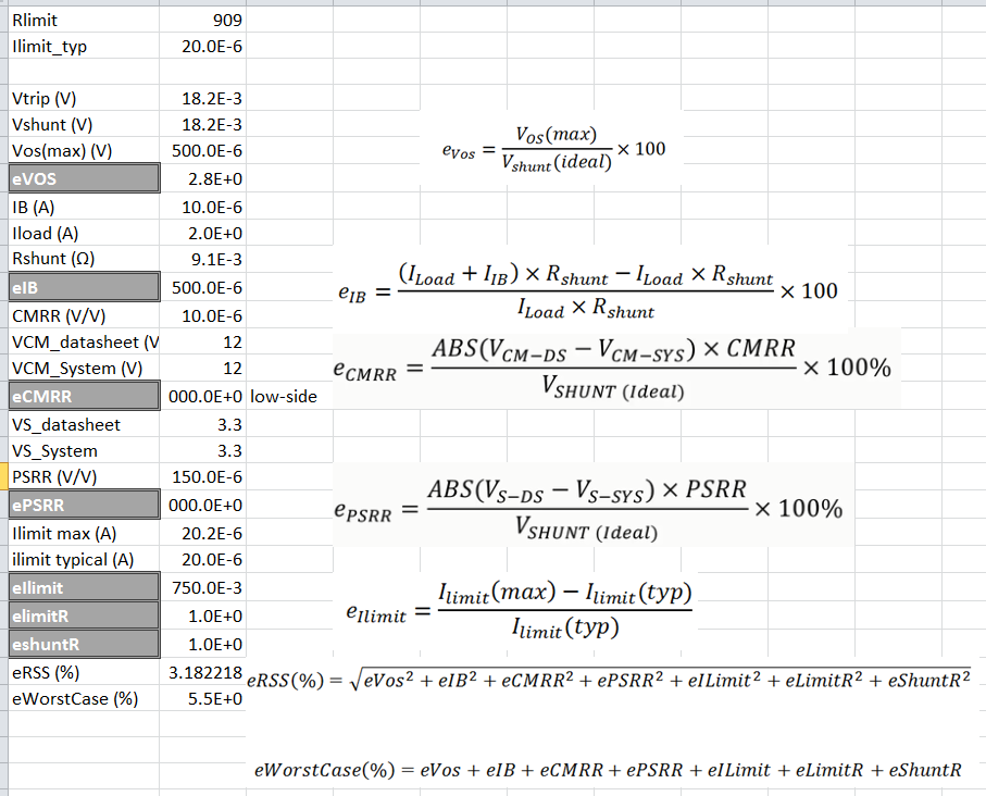
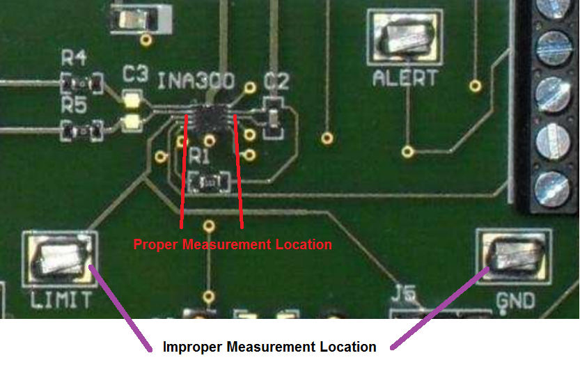
But when i implement this circuit on board then it does not work. problem is that, this circuit does not detect overcurrent. overcurrent set limit is 2A and Limit Resistor value is 909R. we want to check circuit in transparent mode. 

Can you give solution.

  • Hi Priya,

    can you show us your schematic? How is the shunt chosen?

    Kai

  • Hello Priya,

    There are various sources of error that may make the actual trip point higher.  Below are some calculations I did on the possible error you may see in your detection.  As I did not know what your system common mode voltage and power supply were, I assumed they were the same as the conditions used in the datasheet for the listed specifications.  As for your resistors (shunt and limit), I assumed a tolerance of 1%.  After accounting for the possible error, if your device still does not detect, please let me know.

  • Hello Simmons,

    Thanks for your reply.

    I have seen your calculation, which is same as i calculated. but yet, circuit is not detecting the overcurrent.

    I am sharing the schematic herewith for your reference.

    Thanks & Regards,

    Priya Bagal

  • Hi Priya,

    can you please make some measurements for us? Let 2A flow through the shunt and measure the voltages at IN+ input, IN- input and Limit pin.

    Kai
  • Hello Priya,

    I setup a INA300EVM like in the figure below and was able to get the device to trigger.  My setup mimics the voltage conditions your shunt resistor and limit resistor would impose on the INA300-Q1.  At this point I would suspect that either your part is broken or not all of the pins are properly soldered.  So I would inspect your device under a microscope or I would replace the part and assess if a new device will not work.  If you still have issues there may be a layout issue with parasitics or a system issue involving transients destroying your device.

  • Hello Simmons,

    Thanks for your support.
    Yet, issue is not resolved. i checked the PCB layout, that is ok. I have checked all possibilities, like i changed the component, also i have assembled another board and checked it. but problem is remains same. also i have checked it in latch mode then i got same result.
    According to calculations, i got same voltage across the limit resistor and sense resistor. but, why i am not getting the output.
    Please can you solve this issue?

    Thanks & Regards,
    Priya Bagal
  • Hi Priya,

    have you read my post?

    Kai
  • Hello Priya,

    I suspect that the circuit you posted above is part of a much larger system and as such has a power-up sequence. Its possible that during the power-up, the INA300-Q1 suffered an electrical overstress. I would monitor supply pin at startup and see if the voltage ever exceeds 6V. I would also monitor the digital pins if possible. What is down stream of the alert output?
  • Hello Kai,

    Yes I have read your post. I have attached schematic on simmons comment. please check and suggest if you have any solution.

    Thanks & regards,

    Priya Bagal

  • Hi Priya,

    can you please make some measurements for us? Let 2A flow through the shunt and measure the voltages at IN+ input, IN- input and the Limit pin.

    How do you produce the 3.3V for the INA300? Is there noise superimposed to the 3.3V? Is there any cabling involved with your application?

    Kai
  • Hello Kai,

    If we pass 2A current from INA300-Q1, then the voltage at limit resistor is 18mV. We have generated 3.3V by using LDO and the voltage at pin IN+ is 8.4V.

    Could you explain the basic work of INA300-Q1. because still i am not got tje solution.

    Thanks & Regards,

    Priya

  • Hello Simmons,
    My problem is not resolved. could you please explain, how is this circuit work?
  • Hello Priya,

    Presuming you are not overlooking a transient that is damaging your part from connecting the battery or your start up sequence, current passes through your shunt resistor creating a voltage that is compared with the Vlimit voltage, which then triggers the alert to to pull low after 50 μs (since DELAY is tied to ground).  Thereupon, if the alert triggers, the sensed voltage will need to drop 4mV lower than Vlimit, before the Alert will be restored to high.

  • Hello Priya,

    My hardware setup in the lab mimics your conditions and works. Therefore, I suspect there is either a connection issue or your part is damaged. During the overcurrent condition, I need you to probe directly on the INA300 pins to find the voltage differential between device ground and HYS Pin, device ground and LIMIT pin, device ground and ENABLE pin, device ground and LATCH pin, device ground and Supply pin, device ground and DELAY PIN. I also need you to measure the differential between the IN+ and IN- pins. I would like to emphasize that these need be directly on the device pins, which will require fine tipped multimeter probes. In the figure below, I show an example of proper and improper probe placement for measuring the differential between the Limit pin and device ground. Be sure to use the proper placement for all measurements.  Please let me know what voltages you measure.

  • Hello Kai,

    If 2A current flow through the shunt then the voltage at the limit pin is 18mV. the voltage at pin IN+ is 8.4V . we are producing the voltage 3.3V by using LDO UA78M33QDCYRG4Q1. We are not using any cable at that time.

  • Hello Priya,

    Have you managed to probe directly on the pins of the device yet?
  • Hello Kai,

    Yes, i have managed probe directly on the pins of device & i have checked it at test point end also.

    both way overcurrent is not detected.

  • Hello Priya,
    What was the value of the voltage when you probed directly on the pin 1 and pin 2. Please measure these differential. Is there any difference when probing on Test Points (MP2020- MP2021), (MP1001 - MP1002) or directly on pins 1-2?
  • Hello Javier,
    When i probing on Test Points (MP2020- MP2021) then voltage is 18mV and when i probed on test (points MP1001 - MP1002) the voltage also 18mV.

    Regards,
    Priya
  • Hi Priya,

    if you change a bit the 909R resistance, let's say by 20%, in both directions, does then the overcurrent detection work?

    If nothing of all these hints help, then it's time to take a fresh INA300 and check it again.

    Kai
  • Hello Kai,
    I have check all these possibilities like
    1) i have chaged the limit resistor value also i have changed the shunt resistor.
    2) I have checked 4 different INA300 with 4 different board's but afterall the result is same.
  • Hello Priya,

    With the information you provided, we have eliminated any possible connection issues of the device. What remains as a possible explanation is damage due to transients that occur at power up or from the initial battery hookup. If you have long traces or an inductor in line with this device, you potentially may have transient peaks that exceed device limits. There are a few ways to test this. Either you hookup an oscilloscope on the inputs of the device during these conditions or you put tvs diodes on the inputs to clamp them to minimum voltage of ground and a maximum voltage of 36V. You could also place resistors in between the shunt and the INA300 to limit the current going into the input. On this note, measuring the current into the IN+ and IN- inputs may also reveal if the internal ESD structures are damaged and preventing device from correctly measuring the current.

    The one other issue to look into is whatever is downstream of the alert output. If you remove the INA300 and short the INA300 output pad to ground can you pull the downstream input pin low?

    Best regards,
    Patrick Simmons
  • Hello Simmons,

    already i have added RC filter circuit to the input side, but after addition of these circuit the overcurrent is not detected. i have changed the shunt resistor value also limit resistor value. i am using LDO for Vs generation.
  • Priya,

    I have double checked Patrick's setup replicating your and I did not see any issues. If you do not mind can you share your layout. If you do not want to make it public you can email it directly to me or Patrick.

    Also could you please tell me how you are determining the Alert case. Are you using a logic input? Are you measuring the voltage vs GND at the Alert pin? If you are using logic could you please measure the output voltage and see if there is a difference of Alert condition vs non-Alert.

    If you see a difference at the output you may want to check the value of your R106. If there is a jumper installed you could have some non-trigger issues. I measure 2.8V if I shorted the pull up resistor.
  • Hello Javier,

    The issue of INA300-Q1  is solved, now the alert signal goes low when i applied 2A load.

     I have added RC filter circuit of capacitor 100nF and Resistor 22ohm value.

    But now the new problem is arises  that when i have added switch & control circuit before the load connection and then I have applied 2A load, then alert signal does not go low, it remains high after overcurrent limit exceed.

    in short, INA300-Q1 is worked individually, but when it interface with switch and control circuit then alert signal does not go low.

    I have used switch & control circuit as like your reference design of Automotive Precision eFuse Reference Design.

    so please help us.

    Regards,

    Priya

  • Hello Priya,

    By RC filter do you mean at the input of the INA300 or at the output? Can you show schematically how that filter is connected? Have you attempted the circuit without the filter?
    Is the issue the filter or the added control circuitry. I would be concerned how any of these implementations changed inputs to the INA300. Is there anyway to isolate each (filter and control circuit) addition to narrow down the issue.

    I do not see how the INA300 should behave differently. From your initial test where you are verifying that the INA300 works what changes are made that can cause issues. Some things to check:

    1. Power supply limitaitons (Current or Voltage limitaitons)
    2. VCM changes
    3. High or low side sensing
    4. Alternate current paths that bypass your Rshunt resistor.
  • Hi Priya,

    could the whole thing be a soldering issue? When you added the RC filter, could you have improved some of the soldering points of the INA300 and turned an improper soldering joint into a proper on, without necessarily noticing it?

    Kai
  • For those interested in the conclusion of this thread, Priya started a new thread here and that is were all subsequent responses are.