Because of the Thanksgiving holiday in the U.S., TI E2E™ design support forum responses may be delayed from November 25 through December 2. Thank you for your patience.

This thread has been locked.

If you have a related question, please click the "Ask a related question" button in the top right corner. The newly created question will be automatically linked to this question.

LM2907-N: Pulsed inputs level down to 0V

Part Number: LM2907-N

Hello,

I am using this frecuency to voltage converter powered to 15V.

The input is a pulsed signal from 0 to 5V. With this signal leves the converter is not working.

I have to use a signal to a low level below zero. i.e. -0.5 to 5V. In this case de converters works perfectly.

It is a normal behaviour??

thanks

  • Hello Luis,

    If you are using the LM2907-N in the 8-pin package note that in datasheet Section 9.4.1 it states:

    9.4.1 Grounded Input Devices (8-Pin LM2907 and LM2917)

    These devices have one of the two Schmitt-Trigger comparator inputs internally grounded and must be externally connected to the system ground as well. This configuration monitors the remaining terminal for zero crossings.

    Therefore, for the input comparator to change state and the LM2907-N to function correctly the input voltage must cross through 0 V and attain a negative voltage level. That is why you find the -0.5 V to 5 V input signal results in the expected operation.

    If you would prefer not to have to use an input signal that has to go negative, the LM2907-N in the 14-pin package has a differential input and will accommodate this operation. The datasheet states in Section 9.4.2:

    9.4.2 Differential Input Devices (LM2907 and LM2917)

    These devices have both inputs to the Schmitt-Trigger comparator available and broken out to pins 1 and 11. This configuration allows a new switching threshold provided in the case of signals with DC offset or to intake a differential pair and switch based on voltage difference.

    Datasheet Figures 20 through 22 show how a silicon diode and 10 k resistor can be connected to the other comparator input raising the threshold voltage to a positive voltage level. The circuit should operate nicely with a 0 V to 5 V input signal.

    Regards, Thomas
    Precision Amplifiers Applications Engineering
  • I am using the 14 pins package.

    But i have 11 and 12 pins together. I am looking the datasheets figures 20 thougth 22 but i don´t know exactly how to do...

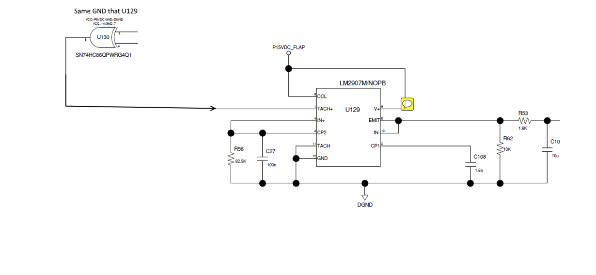
    I have a Logic Gate who generates the pulse signal, and its GND is the same that the LM2907...  I undestand the Diode and resistor structure but i don´t figure out how to fix it...

  • Hi Luis,

    Thanks for sharing your LM2907-N circuit schematic.

    You will need to disconnect pin 11 from ground. Attach the anode of a silicon diode such as a 1N4148 to pin 11. Connect the cathode end of the diode to ground. Then connect a 10 kohm resistor from pin 11 to V+. That will bias pin 11, TACH- about +0.7 V above ground. When the output of the 74HC86 which connects to the TACH+ input transitions from the low state (~0 V), to the high state, the LM2907-N input comparator should respond and initiate the conversion process.

    Regards, Thomas

    Precision Amplifiers Applications Engineering

  • Hello!

    Ok, I had thought something like this.

    Thanks a lot!!! i will try it tomorrow.
  • Problem is Solved now!!!
    Thanks a lot!
  • Hi Luis,

    I am glad the recommended change to the LM2907-N circuit got it working for you.

    Regards, Thomas

    Precision Amplifiers Applications Engineering