This thread has been locked.

If you have a related question, please click the "Ask a related question" button in the top right corner. The newly created question will be automatically linked to this question.

INA826: How to read INA826 Vin(dif Min)

Part Number: INA826
Other Parts Discussed in Thread: LM7705,

I have this plot for my target application:

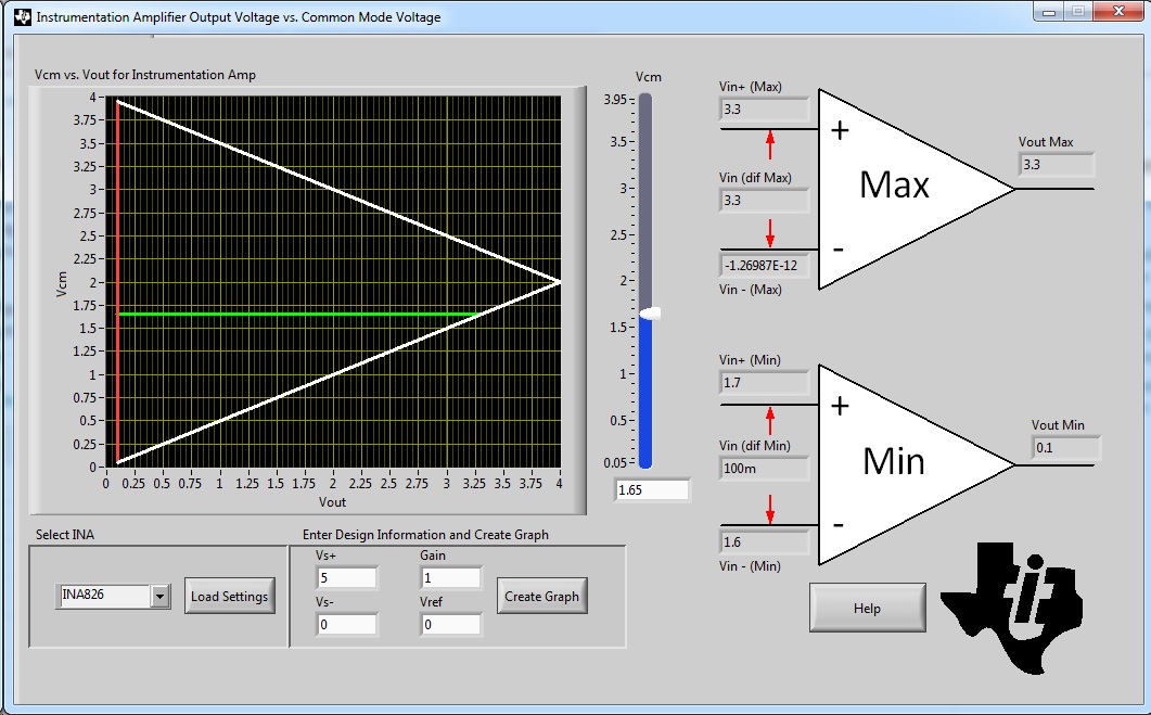
I want a dynamic range as close to 0-3.3V as I can get so I'm looking at biasing this part at a higher voltage.  The Vcm will usually be 1.65V.  The Vref can change since it is user settable.  I noticed that if the Vref is set to 0V the "Vin (dif Min)" value is 100m.  I assume this is 100mV.  My question is, what exactly does this mean?  What happens if my Vin differential voltage in this configuration is lower than 100mV?  Say I set this up and put a 10mV or 1mV differential signal on the input?  What happens?  I thought these devices were designed to receive very small voltages.

The output max and min means the output won't exceed those values, but the input can theoretically be driven with anything so what exactly does that mean?  What happens if I violate it?

What do you do if you want to sense a smaller differential voltage?

  • Hi Robbie,

    keep in mind that the input voltage range is between 0V and 4V in your case with the +5V single supply. Keep also in mind that the output voltage range is between 0.1V and 4.85V. Whatever you choose for the common mode input voltage and the reference voltage, the voltages at the inputs and the output voltage must lie within these ranges.

    Additionally, have a look at figure 11 of datasheet:

    For you the blue curve is valid. This curve also shows that the output voltage cannot go below 0.1V. If you need to produce an output voltage below 0.1V you would need to use a dual supply voltage. But, alternatively, you could set the reference voltage to a higher voltage, 2.5V e.g.. Then your output signal can swing arround 2.5V.

    Kai

  • what does Vin(diff) mean? What happens when you input a smaller differential voltage than what the tool says?
  • Hi Robbie,

    Vin(diff) is the differential voltage applied between the inputs of the instrumentation amplifier. The minimum differential voltage you can apply is based on the output limitations and is related through the gain. Since the output can't swing lower than 100mV away from the rail, you can't apply a signal on the input that would attempt to force the output lower than that and expect a linear output. The output amplifier will saturate at the rail and you will see a constant 100mV signal at the output as you decrease the input. If you were running in a gain of 10, then the calculator would tell you that the minimum differential input is 10mV.

  • So if my vref=1.65v then I can have a smaller input differential voltage?  If I'm trying to measure a 1mv signal with a vcm=1.65 and a vref= 1.65 and vcc(power)=3.3v and a gain of 1 I'm ok because the output is 1.65v steady state.  Then when I get a 1mv I put signal my output changes to 1.651v?  

    If this doesn't make sense how do you measure a 1mv signal whit this amp in a single supply 3.3v system.  I thought the purpose of these parts were to measure very small signals.

  • Robbie,

    The purpose of these parts is to measure a differential signal with a high input impedance. This means you don't load your source, so yes they are ideal for small signals, but every amplifier has input and output limitations and no amplifier can truly swing all the way to the rail. What you have said above is correct and you are able to measure smaller signals because the output stays in its linear region, however if you are not applying negative input voltages then you have essentially thrown away half of your usable output range, but this may be fine for what you need. Otherwise you could use a device like the lm7705 to generate a small negative supply (~-230mV) allowing the output to swing all the way to zero.
  • Ok that makes sense. Thanks for the part number I will look at getting that in my design. On that note, to swing from 0 to 3.3 on the output should I just increase the voltage of the power pin of the amps to get the output closer to 3.3. Similar to what the part that you linked to does for the negative power rail?

    Also, if you agree with the above, do you guys have something that could boost 3.3v up to 4 or 5v to get more dynamic range (closer to 3.3) on the output?

    How worried should I be about noise? I could use a switcher to generate a nonstandard 3 or 4volt power rail for the ina826 chips to accomplish this?
  • Hi Robbie,

    you can do everything you want, add DC/DC-switchers, charge pumps, etc. But this will usually increase costs, board space, supply current, heat dissipation and the need for filtering.

    When using single supply OPAmps the usual way to handle the swing-to-rail limitations is to create a stable bias voltage somewhere between 0V and the supply voltage and reference all the input and output signals to this bias voltage. This bias voltage plays nearly the same role like signal ground in an application powered by a dual supply voltage. Then, it doesn't matter when an OPAmp output cannot go fully down to 0V.

    So, you urgently need a signal output voltage of 0V...3.3V? What supply voltage do you have? How much supply current may flow?

    Kai
  • It isn't too urgent. Most of the input signals to this device will be sub-millivolt from a mems accelerometer and it looks like the small signals are working fine. I was just wondering about options that may allow my customers to have a wider input range. If it was something simple I would probably fold that into the architecture. It isn't a critical path though, the intended functionality is currently there for small signal sensors which is most important.

    In doing some performance testing I got off on this topic because I noticed the input sine wave I was testing with - in a specific configuration similar to what we've been discussing - was not able to get above 30 to 100mV and was stuck below ~3.1V. I didn't know if it could be as simple as change the power supplies and then if I bias the inverting input to 1.65 I could allow my non-inverting input to swing across the whole 0-3.3V range. This would be very handy functionality to have without a doubt. So if it was just grabbing a tiny linear regulator to give me some offset power rails (and a lower ground -> -200 or 300mV) without burning up a lot of power (which I wouldn't expect b/c these are all amps driving high impedance sources ...i.e more amps and and ADC) then I would probably prototype this out and do some testing.

    hopefully this wasn't a convoluted explanation....

    Basically I was trying to figure out if there was a common mode voltage, reference level and power supply configuration that would allow my non-inverting input to swing 0-3.3V and if so how much work would be involved in implementing the changes.
  • Hi Robbie,

    I'm not sure if we've resolved your issue or not, but just to make sure I want to reiterate that the only way to increase your dynamic range here is to increase your supply voltage. If you have a desired signal range then you always have to make sure that your supply range exceeds your desired signal range by at least as much as the input/output limitations of the devices you are using. Even devices we call "rail-to-rail" cannot truly swing all the way to the rail, they can just get really close. Unless you have other devices that explicitly require a 3.3V rail, rather than using an extra power stage I would just switch to a larger supply.

    How concerned you should be with noise depends on how sensitive your system is, what the noise content of your supplies is, and how heavily they will be filtered. At lower frequencies the PSRR of the devices you use will reject the bulk of the noise on your power pins. Adding additional filtering for the higher frequency components can help too.
  • Robbie

    We haven't heard back from you so we assume this answered your questions. If not, post another reply below, or create a new thread if this one has timed-out.

    Thanks
    Dennis