Because of the Thanksgiving holiday in the U.S., TI E2E™ design support forum responses may be delayed from November 25 through December 2. Thank you for your patience.

This thread has been locked.

If you have a related question, please click the "Ask a related question" button in the top right corner. The newly created question will be automatically linked to this question.

INA194: Schematic Review

Part Number: INA194

Hi Team,

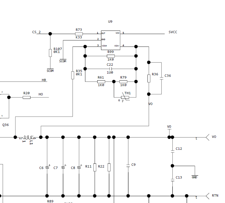
I will need your support to do a schematic review for failure analysis on PN INA194AIDBVR.

  1. L1  - 6.5 – 9 uH, DC Resistance 3.5mOhm
  2. R36 - 5.6 Kohm, 0.1 W
  3. C36 - 1 nF, 50 V
  4. TH1 - 220 Kohm, 210 mW
  5. C22 - 470 nF, 16 VDC

Do you see any issues with the design?

Thanks!

Best Regards,

Alfred Logico

  • Hello Alfred,

    Thanks for reaching out on the forum.  There are a few items to consider with the schematic you posted.  

    The first would be to add a bypass capacitor on the supply pin if there is not one already on the portion of the schematic not shown.  Also, on the actual pcb layout, this cap will need to be as close as possible to the INA194 supply pin.

    The second issue I see is the inductor used as the shunt resistor.  Although the current may not rapidly change through the inductor, the voltage may.  Depending on how signals are switched through the inductor, there could be substantial inductive kickback.  This could produce voltages that violate INA194 specifications. I am assuming this is why R36 and C36 were added. R36 and C36 also raise a concern regarding accuracy.  R36 will increase the error seen from the input bias current as well as increase the gain error of the device. With regard to the input bias current, it is possible that there will be a 16uA*5.6k = .0896V voltage drop across R36, which may be substantial for lower current measurements.  One possible alternative to the current configuration would be to add TVS diode on the VIN+ and VIN- pins.

    Another possible issue, would be the expected Vsense range.  If the device is operated with the intent of measuring currents that produce Vsense voltages below 20mV, your customer could run into accuracy issues outline in the following FAQ:  https://e2e.ti.com/support/amplifiers/current-shunt-monitors/w/faq/3588.measuring-vsense-20mv-with-the-ina193-ina198-products