This thread has been locked.
If you have a related question, please click the "Ask a related question" button in the top right corner. The newly created question will be automatically linked to this question.
Hi,
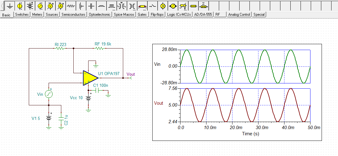
I would like to amplify a vibrations signal. A geoscope detects a ground vibration and outputs a voltage between ±28.8mV within a 10 - 100 Hz spectrum.
The Analog to digital converter that I us, has an input voltage range of ±2.56V meaning that the gain needs to be 88.889
I'm using the Analog Engineer's calculator to determine the resistor values and resulted in the following circuit:
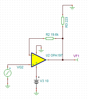
unfortunately this does not amplify my input. Can anyone suggest another circuit that amplifies my ±28.8mV to ±2.56V?
Best regards,
Dukel
Hi Dukel,
The OPA197 is completely capable of handling the task you want accomplished. The issue with your circuit is you are applying a +/-28.8 mV signal to the non-inverting input, and expecting +/-2.56 V output using a single +10 V supply. In order for the OPA197 to function correctly in a bipolar input, output application, it must be powered by a dual polarity (+/-) power supply such as +/-10 V, or using the method described in the next paragraph.
The other method that you can use to remedy the circuit is to apply a positive dc common-mode voltage in series with the input ac signal generator. For example, if you place a +5 V dc source in series with the generator the output will be centered about +5 V. You can see a TINA simulation circuit below. The TINA file is attached.
Regards, Thomas
Precision Amplifiers Applications Engineering