Part Number: LOG114
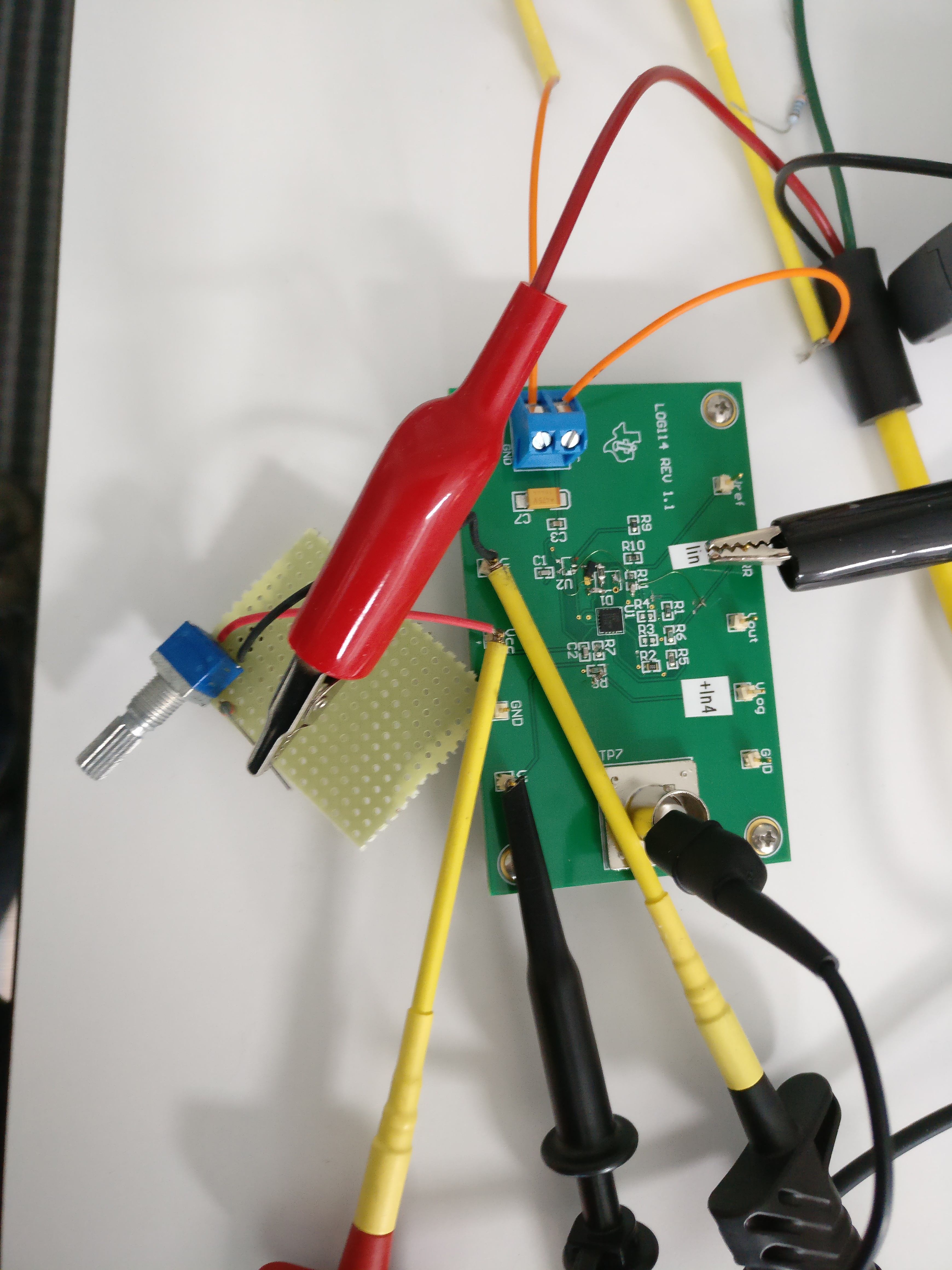
I modified the LOG114EVM board to create this circuit:

For the first step I didn't connect Vlogout to R5 in order to just evaluate the first amplification step.
Unfortunately I cannot get the circuit to work.
V+ = 5V, V- = GND
Vref is correct +2.5V, REF3040 generates 4.096V and instead of a photodiode I use a LDO with potentiometer and series out resistance to define the current. Using a Keysight B2985 current meter I measure this input precisely, it ranges between ~5nA and ~1mA.
However Vlogout always shows the same picture:
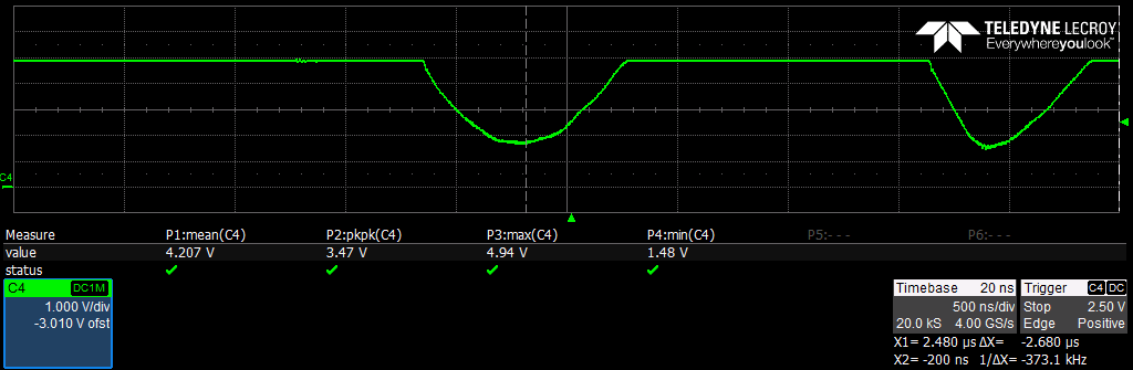
What am I doing wrong? Or did I destroy the OpAmp during my tests?
Obviously my setup is less than ideal (note that I did quite a lot of modifications to the board, however I'm positive that the input lines I1 and I2 aren't connected to anything else. Additional 100pF caps on I1/I2 didn't improve the result in any way.