How do I choose a good pull-up resistor to use on an I2C bus?
This thread has been locked.
If you have a related question, please click the "Ask a related question" button in the top right corner. The newly created question will be automatically linked to this question.
The I2C spec is well known and defined by NXP in the UM10204 specification, available as a PDF here from the NXP website. Section 7 goes into the details of choosing the appropriate pull-up resistor, and this article will provide a real-world example of how to apply the concepts of that article.
When designing a digital system that uses an I2C bus, it is important to choose an appropriate pull-up resistor for the SDA and often the SCL lines. The size of the resistor is determined by a handful of factors. Those are:
If you take a device like the INA226, which accepts a 2.7-V to 5.5-V power supply and can operate in Fast Mode (from 1 kHz to 400 kHz) or in High-speed mode (from 1 kHz to 2.94 MHz). Per the data sheet electrical characteristics table, the input capacitance of the digital I/O pins is 3pF. So with this knowledge, we can use sections 7.1 to 7.4 of the I2C specification to find a range of pull-up resistors that will work for us.
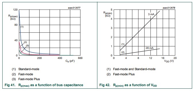
Figure 1 below shows two plots taken from spec UM10204 that we can use to find an appropriate pull-up resistor range.
Figure 1: Figures for finding pull-up resistor values from NXP spec UM10204 |
From Fig 41 (in figure 1 above) we can find the maximum pull-up value based on the speed and bus capacitance. You can see that lower bus capacitance means you can use larger resistors, and likewise larger capacitance means you must use smaller resistors. This is because you need more current to drive a capacitive load to high and low thresholds on the bus, and so bigger capacitors take more current to charge quickly, which means less resistive impedance between the source and the bus line.
From Fig 42 (in figure 1 above) we can find the minimum pull-up value based on the speed of the bus required and the power supply. Lower speed bus speeds require less current because the rising and falling edges don't need to be as sharp, but you do need to have adequate current to pull the bus high in a reasonable amount of time to maintain proper bus functionality. Higher voltages can use larger resistors because I=V/R, so to maintain the same I, R needs to increase to keep pace with the increase in V.
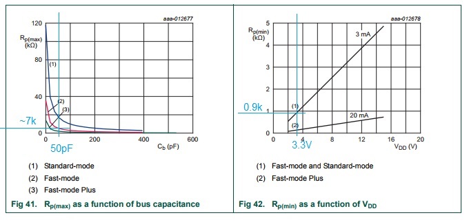
Let's work through an example system. For this example, we'll assume the bus is loaded down with lots of high input capacitance parts, so that the total bus capacitance is 50pF. We'll be running the system in Fast mode at 400 kHz and with a power supply of 3.3V. What pull-up resistor should we choose?
Figure 2 below shows Fig 41 and Fig 42 from spec UM10204 annotated to show how we use the intersections of lines to find the maximum and minimum resistances.
Figure 2: Example method for finding the range of acceptable pull-up resistors for an application |
In Fig 41, we find 50pF on the X axis and draw a line up to where it intersects the "Fast-mode" curve (red). Then we extend a line from that intersection to the Y axis to get the resistance. In this case, it's around 7 kΩ.
In Fig 42, we find the bus voltage on the X axis and draw a line up to where it intersects the "Fast-mode and Standard-mode" curve. The minimum resistor can provide up to 3 mA (which is the minimum sink spec and aligns with the high-power SMBUS spec), so we extend the intersection line to the Y axis to get the minimum resistance. In this case it appears to be about 900 Ω.
So, from this eyeball method, we can see that we need a pull-up resistor between 900 Ω and 7 kΩ. Now how do we choose? If you want lower power and don't expect the bus capacitance to go higher ever, then you can choose the highest resistor possible (7 kΩ) to minimize the power used by the bus. Whenever a bus line is pulled low by a device, there will essentially be a 3.3-V drop across a 7-kΩ resistor, which equates to about 470uA. However, if you expect more bus capacitance, or a change in voltage supply, or want to squeeze every bit of speed and performance out of the bus, then you may want to choose something closer to a 900-Ω resistor.
TI makes no warranties and assumes no liability for applications assistance or customer product design. You are fully responsible for all design decisions and engineering with regard to your products, including decisions relating to application of TI products. By providing technical information, TI does not intend to offer or provide engineering services or advice concerning your designs.