This thread has been locked.

If you have a related question, please click the "Ask a related question" button in the top right corner. The newly created question will be automatically linked to this question.

INA169: INA169 with MSP430F5329

Part Number: INA169
Other Parts Discussed in Thread: LMP8645, LM324

Hi, 

So the issue is that when measuring with the ADC the gain of the INA169 will change according to the sample and hold time. As I understand this has to do with the fact that the INA169 has a current output and  its gain is controlled by the RL. RL impedance will change when sampling and thus the gain is not as predictable as it should. This is what I perceived. My design is an exact copy of the one showed in the datasheet. The ina output goes from RL directly into the ADC input. Also, I had a weird glitch when measuring with a multi-meter. After measuring the voltage across RL while in operation, the INA would change its gain. Even after shutting down the circuit the gain would remain higher than intended. 

  • Hi Werner,

    I don't think that the INA169 is the issue here, but rather the succeeding circuit. What ADC is connected to the output of INA169? What interface circuit does the input of ADC expect? Have you thought about connecting a filter cap in parallel to RL? Have you read section 8.2.1 of datasheet ("Buffering Output to Drive an ADC")?

    Kai
  • Hello Werner,

    Thanks for considering to use Texas Instruments in your design.  As you have alluded to, there can be gain issues when connecting directly to an ADC (that diagram in the datasheet needs to be updated).  This is because of the ADC input impedance.  If the input impedance is not sufficiently larger than RL, it is possible that the ADC will siphon off a substantial portion of the output current from the INA169.   To correct this, you will need to use a buffer. If you are hard pressed for board space, you may want to consider the LMP8645, which is a similar architecture with an output buffer included.

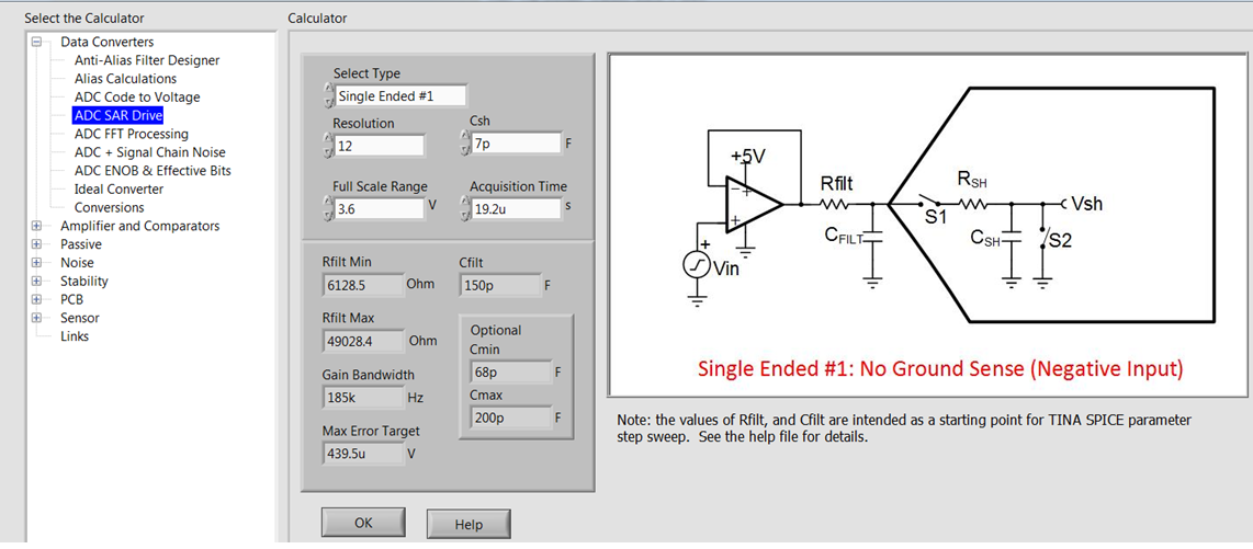
    Aside from the buffering aspect, we typically recommend placing a charge bucket filter on the input of a SAR ADC.  This help stabilize the ADC input/current shunt monitor output when the ADC starts sampling.  We actually have a calculator you can download, that will help you determine the appropriate values to use for the filter.  That can be found here: 

    http://www.ti.com/tool/analog-engineer-calc?keyMatch=analog%20engineers%20calculator&tisearch=Search-EN-Everything

    This calculator actually includes alot of other tools, so to navigate to the filter calculator, follow the diagram below:

  • Thanks a lot. I was currently testing an LM324 as this is the one I had at hand. I found out that I obviated the bucket capacitor and was having bad readings. I will consider changing to the LMP you suggested. It looks great. Again, thanks for your detailed explanation.