This thread has been locked.

If you have a related question, please click the "Ask a related question" button in the top right corner. The newly created question will be automatically linked to this question.

INA300-Q1: Alert signal does not go low when we added switch and control circuit

Part Number: INA300-Q1
Other Parts Discussed in Thread: INA300, INA381, LM555, INA206, INA207, INA204, INA205, INA203, INA208, TIDA-00795

Hello,

 I am using current sensing IC INA300-Q1 for overcurrent sensing for 2A limit. if I checked this IC independently, it works, it goes low after 2A current sensed. i have added switch and control circuit before load. that time the alert signal does not go low, it remains on, please look into this issue and suggest any solution. I  have attached schematic herewith.

INA300-Q1.docx

  • Priya,

    If you remove R1019 or place a large resistor does the Output of INA300 PIN 5 go low during your alarm condition?  This will eliminate the input or setup of the INA300 or the output in this circuit INA300.

    If the Alert pin does pull low you need to look at your circuit for the switch and evaluate the circuit as described in the TI Design you got this circuit from.

    If it is the input side or the setup of the INA300.  We need to eliminate the difference from you independent testing the INA300 to the conditions of the INA300 in your applicaiton.  I mentioned some things to check.

    1. Differences in power supply and power supply limtations
    2. Input Common mode differences
    3. Paths of current on your board that create a different Vsense at the INA300 inputs.

  • Hello Javierm

    As per reference design   http://www.ti.com/tool/TIDA-00795 , the alert pin of INA300-Q1 goes low when 2A load applied. but according to that circuit latch pin is high, so my circuit didn't auto-recover after error condition is removed. in my design, we required the auto-recovery of circuit after fault condition is removed. so how I can implement it. if i keep this circuit is in transparent mode that independent INA300-Q1 can work .. but when i connect the switch & control circuit in between load and INA300, then the alert pin is remains high after overcurrent detection. I dont want manual reset switch for enable pin reset. is there any solution for it.

  • Priya,

    I believe I now understand the issue. In transparent mode the INA300 will go low during an over current event. Then it will open the switch and immediately determine that the over current condition is not there and return to high. To determine if this is correct you would need to place an oscilloscope at the output and make sure this is the case. This should then regulate the current to ~2A. To fix this you may need to add a delay or another control. I will look into another solution.
  • Hello Javier,

     I hope you understand my problem, please check it and suggest another solution. I need to auto-recover the circuit after fault is removed.

    If I place the circuit in transparent mode and  I connect the load directly to IN- pin of INA300-Q1 then circuit has detect the overcurrent (i.e. cutoff at 2A load). when I decrease the load or remove the load then it is automatically recovered it.

    But problem is that, I have put the some switch and control circuit ( likewise http://www.ti.com/tool/TIDA-00795 ) between pin IN- of INA300-Q1 and load. in that case when  I applied 2A or more than 2A load, but alert signal does not go low, it is remains high.

    In Latch mode, alert signal goes low, but it didn't recovered after load decreased or removed. It is remains high until we didn't power off.

    I hope you understand my circuit requirements, The alert signal should be go low, once overcurrent event occured and it should be auto-recover once load decreased or load removed.

    so please suggest, what i do? 

  • Priya,
    We are working on getting the hardware looking at options for you. Please give us a day or two to see what solutions we come up with.
  • Hello Javier,

    I am awating for your reply.

  • Hello Priya,

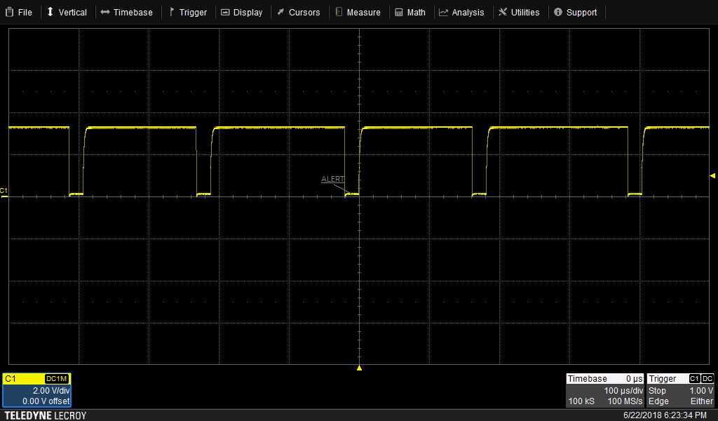
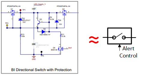
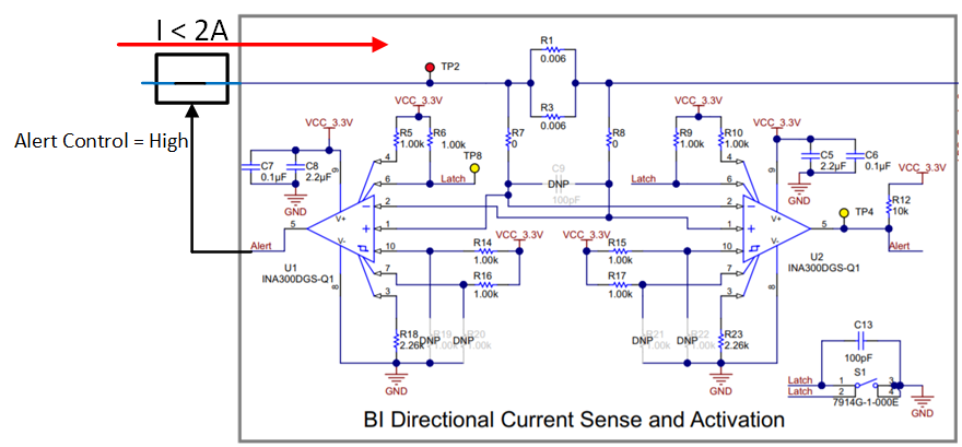
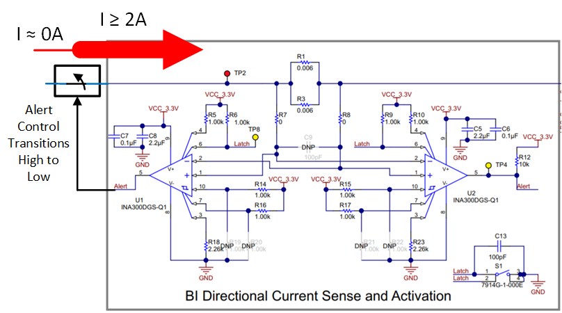
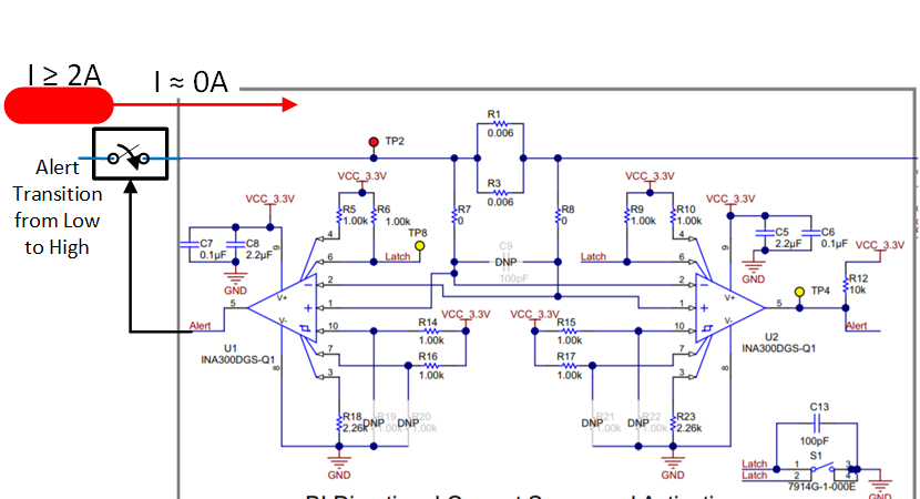
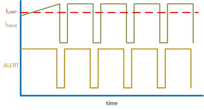
    We tested the setup you referenced (tidubk1b) with a few modifications in the test conditions. In our setup, we used 150 ohm Limit resistors to set the threshold current to 2A for a 0.003 ohm shunt. Our common mode is set at 6V. In this instance our ALERT LED dimmed when the device was operated in transparent mode (Latch pin shorted to ground). This corresponds to the ALERT toggling between on and off with a large duty cycle (ALERT typically high, see Figure 1). You could alternatively observe this through a DC measurement with your multimeter, which should indicate that the ALERT is a few hundred mV lower than 3.3V. To illustrate why this occurs, we first will simplify the bidirectional switch with protection to a simple switch symbol (figure 2). While the current is below the over-current condition, the device passes the current (figure 3). After the threshold is crossed, the ALERT pin transitions to low after a small delay and thereupon the gate closes after some additional delay (figure 4). At this point only a trickle of leakage current passes through to the sense pins. Since the current level is way below the threshold, the alert re-asserts high (figure 5). Then the cycle repeats itself until the upstream source provides a smaller load. Figure 6 illustrates the signal behavior with ISense included.

    Figure 1: Measured Alert Signal

    Figure 2: Bidirectional Switch Simplification

    Figure 3: Bidirectional Switch Operation for Current below threshold

    Figure 4: Bidirectional Switch Operation when limit threshold exceeded

    Figure 5: Bidirectional Switch Operation after INA300 cut-off from Load

    Figure 6. Signal Transient Response

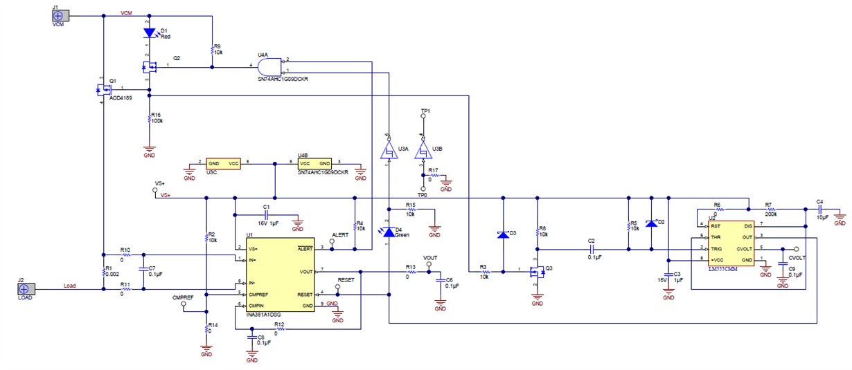
    The proposed fix for this circuit would be to implement a circuit like what is shown in the following schematic, with the INA381 swapped out with an INA300. (Example Circuit). The following circuit essentially allows the off time to last considerably longer before automatically allowing the load to pass through the switch. This circuit accomplishes this by ANDing the ALERT signal with an output signal from an LM555 timer. The CVOLT capacitor determines the duration the fuse switch is off. You can increase this value to increase the time off period. 

  • Hello Patrick,

    Thanks for your reply, Please could you share the INA300-Q1 Schematic with your changed values of sense and limit resistor.
    But i don't want manual switch for alert signal reset function.
  • Hello Priya,

    For my test circuit, I made the following changes:  R1, R3 = .003 ohm; R18, R23 = 150 ohm; Latch = GND (Button always pressed for transparent mode).

    The schematic for an example automatic reset switch circuit can be found here.

  • Hello Simmons,

    I have two queries,

    1-   As you suggesterd in above comment, i have changed resistor values and latch pin connected to ground but at that time , alert signal goes low but the output MOSFET gets heated very fast and it is the chances of circuit damaged.

    2-  INA300-Q1 having very fast delay responce time i.e. 100us. can you suggest the IC for low responce time of delay.

  • Hello Priya,

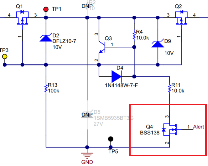
    1 - I am not sure what your query is here.  If the ALERT is asserted and BSS138 MOSFET is turned on, I suspect that alot of current will pass through its relatively small RDSon if you removed the 10kohm resistor that should be in series with it.  If you did not remove it and it is still getting hot, there may be another issue.  A heat sink will probably help, but that will not fix the root issue.  You are talking about the MOSFET pictured below right?

    2.  We only have a few other current sensing devices with comparators included in them.  Those with a programmable delay include the INA203, INA204, INA205, INA206, INA207, and INA208.  Otherwise did you ever get a chance to try this circuit we recommended above?

  • Hello Priya,

    I hope your project is coming along better now. If not, please let us know if there is anything more we can do to help you.
  • Hello Priya,

    Can you clarify which mosfet you were talking about? Also do you need an explanation of how the above delay circuit works?
  • hello Simmons,

    I am talking about MOSFET Q2, which was heated very fast, when we will pass 2A current in this circuit.

    I have attached INA300-Q1 schematic herewith, in that i made some changes like, i want to keep this circuit in transparent mode so i connected latch pin to ground as discussed with you. but with this corrections alert signal goes low, once 2A overcurrent detected. but that time MOSFET Q2 is heated very fast.

    i want to keep circuit in transparent mode because i need auto-recovery function after overcurrent is removed.. in latch mode, the alert remains low, if overcurrent condition is removed.

  • Hello Priya,

    So only Q2 gets hot? When it gets hot, what is the differential across the drain and source of Q2? Typically the part should get colder when the current is cutoff. More current would make the part get hot. If you are using a IPD90P04P4L-04, that part is rated for 90A, so it should be ok. Did you also copy the layout we have in TIDA-00795? In that layout we have fairly large copper planes underneath the MOSFET to dissipate heat.

    I understand you want to keep the transparent mode. That is why I shared that above circuit, you simply replace the INA381 with the INA300 and make a few adjustments and you have an overcurrent protection circuit with a longer delay.
  • Hello Priya,

    Were you able to check any of the items I mentioned in my last post?