This thread has been locked.

If you have a related question, please click the "Ask a related question" button in the top right corner. The newly created question will be automatically linked to this question.

INA233: INA233 Re-Calibrating

Part Number: INA233

I am using INA233 for one of my projects.

I have 2 queries as below:

1. The formula for correcting the calibration in section 7.5.5 of INA233 datasheet is something like:

Corrected_Full_ Scale _ Cal = trunc ( Cal * MeasShuntCurrent / Device _Reported_ Current ).

I suppose the current measurements (the actual and the device reported) should be in the raw format. If so, the Actual measured current across the Shunt should be converted to the raw value from Amps using the co-efficient m,R and b? 

Can anyone confirm this?

2. Consider this scenario,

Current_LSB = 1 mA/bit

which gives m = 1000, R = 0, b = 0;

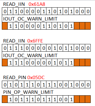
So for setting the over current limit of 25 Amps, is get the raw value of 25000d = 0x61A8. 

My question is, what if I want to set the over current limit to 28.67 which gives a raw value of 28670d = 0x6FFF as the IOUT_OC_WARN_LIMIT (4Ah) has bits [2:0] set as 0 to default. 

  • Hello Gunj,

    Thanks for considering to use Texas Instruments.

    1. Yes you should convert to the raw value using the coefficients m, R, and B found in Equations 3 and 4 of the datasheet.
    2. According to section 7.5.3 of the datasheet, the warning registers only use the upper 12 bits of the internal ADC. So if we convert your 28670 to binary we get: 110111111111110. Thereupon we will remove the lower 4 bits to get 11011111111. From that point we plug those bits, into the register bits labeled IOx (see page 25, for example IO1, IO2, ...,IO8). Thereupon your register value should be set to:
    011011111111000 (14328d). This should then correspond to an adjusted OC limit of 28.656A
  • Thanks for replying. I think I understand this.

    Please confirm the below scenarios if I am getting it correctly:

    1. To set the current limit of 25 A 

    I convert it to raw -> 25000d or 0x61A8.

    Mask the upper 12 bits to get 0x061A.

    Then left shift it by 3 bits to get 0x30D0 or 12496d. -> This value should be written to the register to get 25A current limit warning

    2. To set the current limit of 28.67 A

    I convert it to raw -> 28760d or 0x6FFE

    Mask the upper 12 bits to get 0x06FF

    Then left shift it by 3 bits to get 0x37F8 or 14328d  -> This value should be written to the register to get 28.67A current limit warning

    3. To set the Power warning limit to 600.2W with Power_LSB=25mW/bit, m=40, R=0, b= 0 

    I convert it to raw -> 24008d or 0x5DC8

    Mask the upper 12 bits to get 0x05DC

    Then left shift it by 4 bits(as its from 4:15 in 7.6.2.7) to get 0x5DC0 or 24000d

    So basically, this Power limit set value can be written as it is to the register -> (0x5DC8 & 0xFFF0) should be written to the register to get 600.2W power limit warning

    Kindly confirm if this I got it right. 

    Thanks.

  • Hello Gunj,

    I actually made a mistake in my last post.  After confirming this with another teammate, the proper protocol for the getting the correct warning register value would be to mask bits 3-14 of the desired value on the 16 bit scale.  The MSB refers to the sign bit and is ignored because the trip point will be used for both forward and reverse current.  See the following diagrams for how the warning registers will look for your above cases.

  • Hi Patrick,

    Thanks for helping me out.

    I see that the PIN_OP_WARN_LIMIT register has [15:4] as the data and [3:0] is reserved from the datasheet.

    So I assume, I mask [15:4]  of the Power threshold's raw value.

    So my Power threshold of 600.2W -> 0x5DC8 becomes (0x5DC8 & 0xFFF0) = 0x5DC0.

    So ultimately, I don't need to do any masking for writing to the registers as the other bits have no effect.

    Thanks for the help again.

  • Hey Gunj,

    Glad to be of service. Reach out if you have any additional questions.