This thread has been locked.

If you have a related question, please click the "Ask a related question" button in the top right corner. The newly created question will be automatically linked to this question.

LM358: Strange behavior with output offset and power consumption

Part Number: LM358

Hi all,

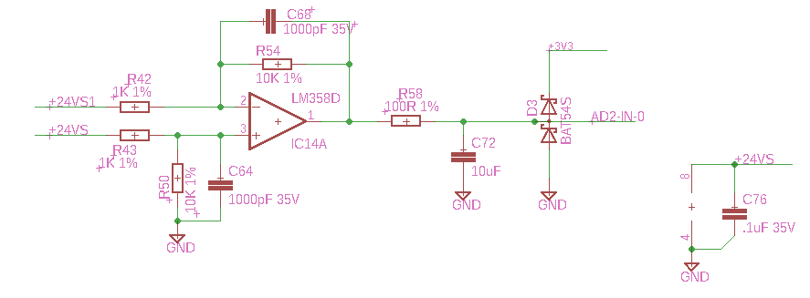
I am using an LM358 to measure the differential voltage across a 0.1 ohm resistor that is functioning as a high side current monitor. 

The schematic is below, but the .1 ohm resistor is not shown (it is located between the two inputs (+24VS and +24VS1)).

Initially there is no current flowing through the current sense resistor, which leaves both inputs essentially connected to the + rail. The voltage measured at the inputs is in fact exactly equal to the op amp positive supply voltage.

I believe this circuit satisfies the common mode voltage requirement of the chip because the voltage divider on the input causes the actual op amp inputs only see 21.8 volts which is 2.2 volts below the +24V supply voltage.

According to the spice models, the output of this circuit should be about 60 mV because that is as close as the op-amp can get to the negative supply voltage (which is ground in this case). However, what I am actually reading is 750-800 mV. I have removed all the capacitors and the output protection schottky diodes, they make no difference.

I am trying to find some explanation as to why the output voltage offset is so high when the inputs are both right at the plus supply rail.

The other strange thing is that the opamp  is consuming roughly 22 mA and is getting slightly warm.

Any suggestions?

Thanks,

Don

  • Don,

    Input common mode is OK at 21.8V.  For an output of 60mV requires the op amp to sink the current provided by R42 and R54. Current flow is (24V - 0.06V) / (1k + 10k) = 2.176mA

    Looking at figure 9 of LM358 datasheet. I marked 2.2mA which is about 0.8V

    This explains the output voltage for no sense resistor current. Do you have any 3.3V op amps free? Adding one to this circuit could greatly improve the output dynamic range. 

    22mA supply is far too high for this circuit. Is the other amplifier output shorted?

  • Hi,

    Wow, that totally explains the offset. Thank you very much for you response. Since I am measuring DC, I think I can go way up on the values of the resistors, maybe like 500K and 5K instead of 10K and 1K. That will reduce the current by 500X down to .02 mA which looks like it gets into a much better output voltage.

    As far as the supply current goes, both amplifiers are actually doing exactly the same thing with the same schematic. The supply current I mentioned was going into the whole measurement circuit, which would be both op amps and the voltage dividers on the + inputs of the op amps, so that would partially explain the power consumption, it would be 9 mA just through the 4 11k paths.

    Could you elaborate a little bit on how to use the additional 3.3 V op-amp?

    Thanks,

    Don
  • Don,

    I haven't built this but it came to mind today. There is also an alternate output at diode's anode.

    The 3.3V op amp needs to be RRIO.

  • After trying a lot of different things I eventually realized that I would never get good enough Common Mode Rejection with what I was trying to do. Even if I used .1% resistors for the feedback and input resistors a Monte Carlo analysis still shows that my output error is significant because the Common mode voltage (24V) is so much greater than what I am trying to measure. Then I discovered the TI INA4180A3PW which is made for exactly what I am doing and solves my problem perfectly. I built a prototype with it and it works great.

    Thanks for all your help.

    Don