This thread has been locked.

If you have a related question, please click the "Ask a related question" button in the top right corner. The newly created question will be automatically linked to this question.

INA196: Check for circuit connections

Part Number: INA196
Other Parts Discussed in Thread: INA195

Hi

My client is currently applying INA196.

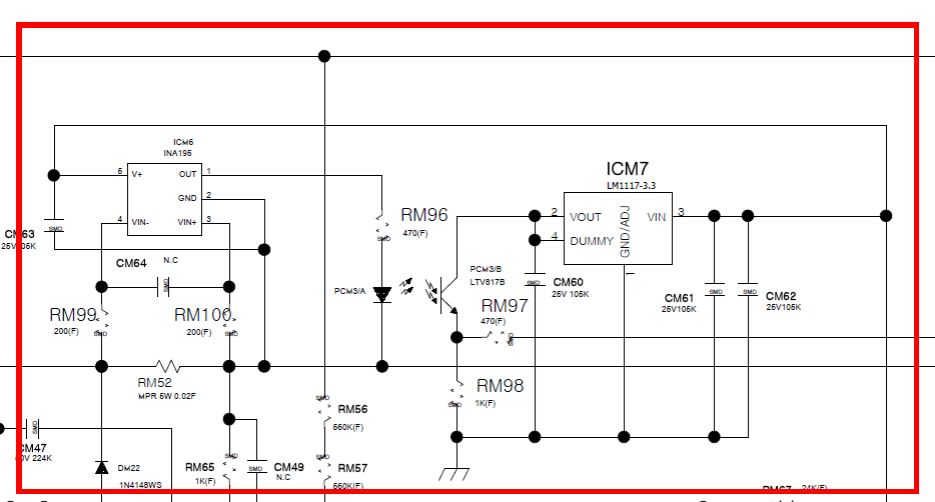
Make sure that there is no abnormality in the connection of the current detection part of the circuit.

The INA195 detects the current flowing in the (+) line. Is it that the current flowing in the GND line can not be detected?

Is only INA196 able to sense the current flowing through the GND line?

  • Hi KIM,

    Do you know if the INA196 is used for low-side (Vin- = GND) or high-side (Vin+ = Vbus) sensing in this application? Vin+ should NOT be connected to GND (pin 2) of the device. GND should be connected to the system ground.

    RM99 and RM100 may be excessive. If you find resistors here necessary, try 10-100Ω.

    The sensed current should be within a range high enough to deliver an output capable of driving the LED but low enough to stay beneath the device’s claw curves. Also ensure the LED does not require too much current to drive the photo-transistor. The INA196 can source limited current depending on the output voltage as shown in the following datasheet curve:

    These values depend on the supply voltage used, but if output current increases too much to drive the load, output voltage will decrease resulting in inaccurate readings.

    Additionally, calibration of the photo-transistor circuit may be necessary. Hopefully this is helpful!

    Thank you for your time,
    Manuel Chavez