This thread has been locked.

If you have a related question, please click the "Ask a related question" button in the top right corner. The newly created question will be automatically linked to this question.

INA114: INA114 or INA121 ?

Part Number: INA114
Other Parts Discussed in Thread: INA121, INA828

Hi 

I have an application here I get a voltage measurement to be done at pins of a resistor of 300K powered by a fixed current source

The voltage maximum will be 0 to 10V 

I must of course not disrupt the current in the resistor 

So I plan to use an instrumentation amplifier like the INA114

i've seen also the INA121 and others

So .. which model shouild be better choice for my application

Thanks in advance

Regards

  • Hi Claverie,

    I do not know what is important for your application, but any instrumentation amplifier will have sufficiently high input impedance to fit, but don't forget you have to make sure there is a path for bias current to return to ground. You need to determine what is important in your system, i.e. what kind of gain and bandwidth you need, how much noise you can tolerate, what your error budget is, etc. Given the large resistor value you will likely want a device with low bias current. The INA121 has low bias current, so it might be a good fit. The INA828 is another option, but it may be overkill for your measurement.
  • Hi and thank you

    my application is very simple

    the aim is to measure resistors from 10 ohms to about 300 K with max 10 V when 300 K (so current source about 30 uA)

    No probleme of bandwith but need to be stable with gain 1 

    The noise should be lowest as possibile I need to get precision about 5% on measurement with a voltmeter card behind the INA

    Thanks

  • Hi

    I've recevived and tested today an INA114


    I've got a problem I can't explain

    When I put a power supply at V+ inpuit pin the INA works perfectly and follows it's input

    if I release the power and connect the resistor to be tested an error appears between value of input and output of the INA

    Like an offset ?

    some values measured (by changing R15 value the resistor to be tested)

    INPUT / OUTPUT  of INA114

    2.77  / 2.801

    5.145 / 5.226

    7.07 / 7.12

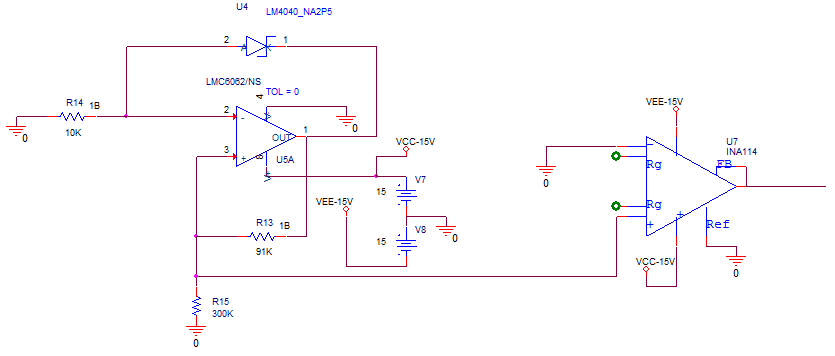
    attached is the schematic with the current source

    the value of current is not disrupted by INA

    I use the DIP 8 pins version of the INA114 so the FB pin is not available.

    Do you get an explanation ?

    Thanks

  • Hi Claverie,

    What are you using to measure these values and how do you have this built up? The bias current of the INA114 should not be significant enough to produce this much offset error.

    Why are you using an INA for the buffer stage though? A simple op amp buffer should suffice here.
  • hi and thanks

    Ive tested whith an operational amplifier mounted in differential amplifier but the input resistors even with 1Mohms on each disrupt the value of 300 kohms

    so I Don't understand which buffer you propose ?

    Ive tested INA due to their very high iinput impedance ? I'm false?

    to answer your questions I use multimeters high impedance like fluke and others to measure input and output at the same time on the INA

    as you I don't thing about a problem of biais current whch shoul be low

    and the values are measured directly on the pis of the INA

    I've checked also the right value of the ground beteen pins

    Thanks

  • Hi Claverie,

    You do not have a differential signal, so unless your ground potentials are different there is no reason to use a difference amplifier or INA, you could get away with a simple non-inverting op amp buffer. The front end of an INA is essentially 2 buffers to preserve high input impedance, you are looking into the non-inverting terminal of an op amp.

    Are you breadboarding this circuit or is this on a pcb? If you have soldered components, it's possible that you are seeing contamination from flux, which can cause bias currents to look much larger than usual. You may also want to test another device to be sure you haven't damaged anything. What is the output of the INA driving?
  • hi and thanks
    effectively I've only wire the INA on a prototype board so without solder only wires
    I've now pout it on a PCB and it seems to be better
    I will keep you inform
    thanks Again
  • hi
    all is ok now
    thanks for your support
    regards