This thread has been locked.

If you have a related question, please click the "Ask a related question" button in the top right corner. The newly created question will be automatically linked to this question.

Stability on differential buffer driving capacitive load

Other Parts Discussed in Thread: LF356

Hello,

I got a question regarding the calculation of the stability of a differential buffer consisting of 2 parallel non-inverting buffers, which drive a capacitive load. (See picture). Is there any possiblity to calculate the stability of the two buffers analytical? And can I calculate the stability of this circuit by looking at only 1 op-amp, which drives the capacitive load connected to ground?

I would like to thank in you advance.

Regards

Alexander

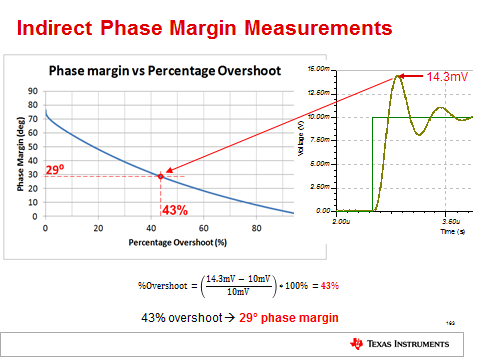
  • The simplest way to determine stability of any circuit is to apply a small signal square wave (e.g. 10mV) and look at the output for overshoot as the signal settles to its steady-state value;  an overshoot of 25% ot less indicates a stable system where phase margin is 45 degrees ot greater - see below.

    For more details on how to analyze stability of the circuit and ways to improve it, please click on the following link:

  • Thanks for your answer. The two op-amps are going to be composite op-amps with a very high open loop gain. Is there any possibilty to create bode plots for those two op-amps? My main concern is, that there are two feedbacks loops which somehow interact because of the capacitance and the output resistance of the op-amps.

  • Hi Alexander,

    which OPAmp are we talking about?

    Kai
  • Actually each op amp consists of 2 LF356 cascaded for a higher open-loop-gain (I'm sure there are better op's today). The open loop output resistance of each of these buffers should be about 50 ohm. The high-open-loop-gain is needed because the circuit has to be quite precise. I'm aware of other effects like CMRR, which would reduce the accuracy of the buffering.
  • Hi Alexander,

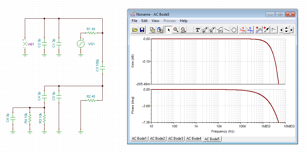
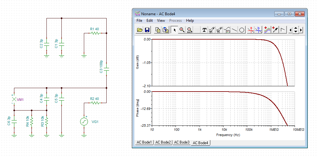
    the following pictures show the result of a simplified phase stability analysis:

    u1.TSC

    u2.TSC

    Kai

  • Basically this means, that I can look at only 1 op-amp and ignore the gain of the other for the stability analysis and I have to do this for both op amps individually? Is there any further literature on this procedure?
  • Hi Alexander,

    yes, that's what I think. I would use this simplified phase stability simulation to see whether the phase margin is violated in the region of unity gain frequency. If this is the case, trouble might be expected. Of course, this is only a rather static simulation. But if the phase margin is eroded for a "static" model, then this will not be good news for a "dynamic" OPAmp as well. :-)

    Make no mistake, I would also use the technique Marek mentioned. Each technique gives another facet of the issue and helps to find out, what's actually going on.

    Kai

  • Alexander

    We haven't heard back from you so we assume this answered your questions. If you need additional help, just post another erply below.

    Thanks
    Dennis