This thread has been locked.

If you have a related question, please click the "Ask a related question" button in the top right corner. The newly created question will be automatically linked to this question.

Crossover distortion?

Part Number: OPA544
Other Parts Discussed in Thread: LM675, OPA541

Below is a customer issue:

"I am currently using the OPA544 for a project which requires a high frequency sinusoidal output. It seems that this op amp has a “small hiccup” at the 0 crossing where I believe the transistors are switching. Does TI have a similar op amp that can switch at a faster rate which makes this hiccup effectively go away? I am wanting an op amp that can output at least 2A, but more would be better, I’m currently using +/- 12V rails for the supply. The sin wave I need to generate needs to be at least 20kHz, but I am hoping to be able to achieve over 1MHz."

LM675 was suggested as an alternative and new issues arose, please see below:

"Once again, I’m not sure what to call the characteristic for how long it takes the device to switch from positive to negative, so I’m not sure what to look for on the datasheet. Are you able to tell me if the OPA541 will have switching times in the nano second range? The LM675T takes about 2 us to switch over 0. It would be great to find something faster, the LM675T was also showing some odd behavior that I didn’t expect to see. When I ran the output through my DMM, it became un-usable and unstable, and large amount of distortion were put on my +in signal line? This behavior was simply not present when using the OPA544."

Any explanation as to the possible crossover distortion and instability taking place would be appreciated. As well, are there any part recommendations to fit the customers needs?

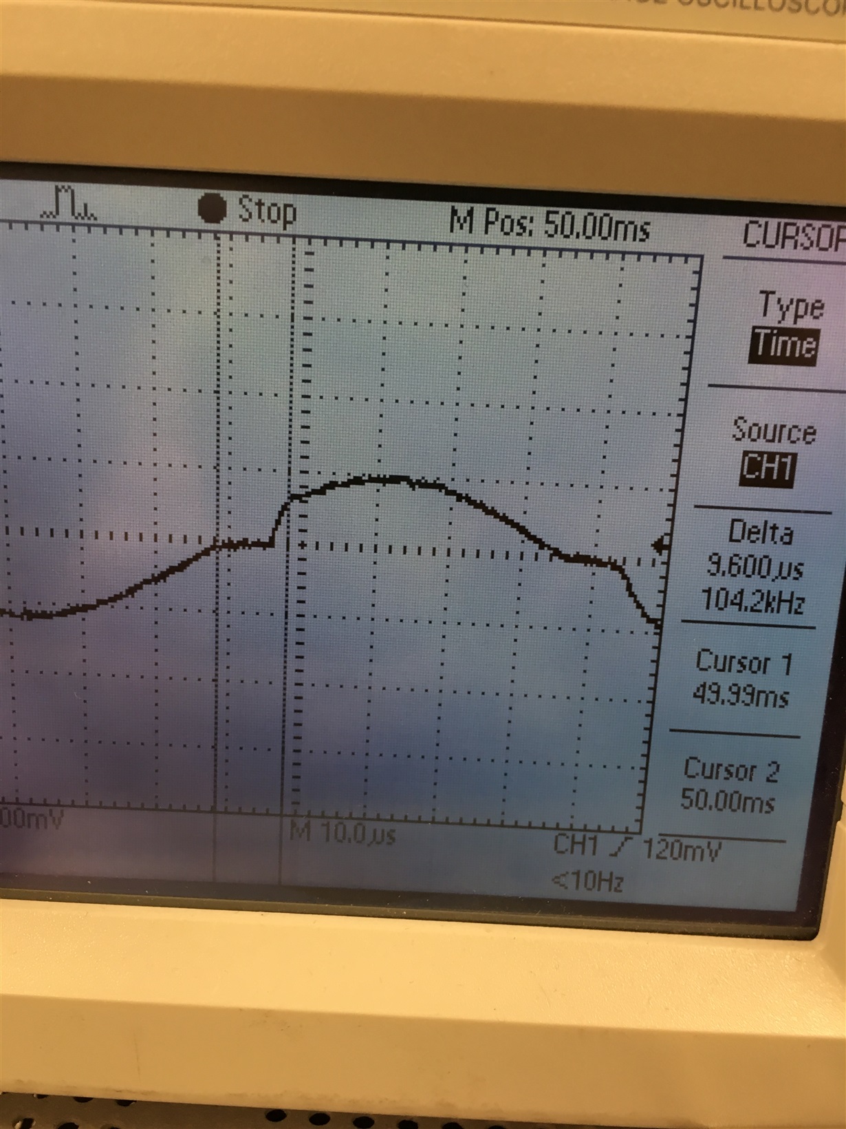
Below is the distortion taking place using OPA544.


  • Hi Claire,

    can you show us a schematic of the circuit that showed an "odd behaviour" and became "un-usable"?

    Kai
  • Hello Claire,

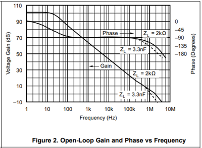
    Every op amp, including the power op amps, has an open-loop gain/phase vs frequency response similar to that shown below for the OPA541. The actual gain and phase at a frequency will be unique for each different op amp because of the different designs and processes; however, the OPA541 curves are useful for illustrative purposes.

    The OPA541 open-loop gain (Aol) at very frequencies is about 100 dB. If the op amp is used in this frequency range and a moderate to low closed-loop gain (Acl) is needed, there is high loop-gain available to assure high gain accuracy and to reduce output distortion. However, as the frequency of interest is increased the Aol decreases at a -20 dB/dec rate and falls to 0 dB around 2 MHz. Thus, the Aol decreases at higher frequencies leaving less loop-gain available to reduce output distortion.

    Your description of the OPA544 "hiccup" and image of the LM675 output appear to be output crossover distortion. This is normal behavior for a class AB output stage used in most op amps. This kind of distortion is much reduced when the loop-gain is very high at the lower frequencies, but increases as the Aol decreases.

    If the maximum frequency can be kept in the 20 to 50 kHz range, then reasonably good performance may be attained with the OPA541, OPA544 or LM675. The slew rate would also have to be considered to make sure it supports the needed output voltage swing without introducing slew rate limiting. Do note that the LM675 is designed to be used in applications where the Acl is 10 V/V, or greater. Anything lower then instability is likely to occur.

    Applications where high output current capability and low distortion are required at higher frequencies often employ a wideband RF power amplifier; one designed to deliver watts of output power at low distortion levels.

    Regards, Thomas

    Precision Amplifiers Applications Engineering

  • Hi all,

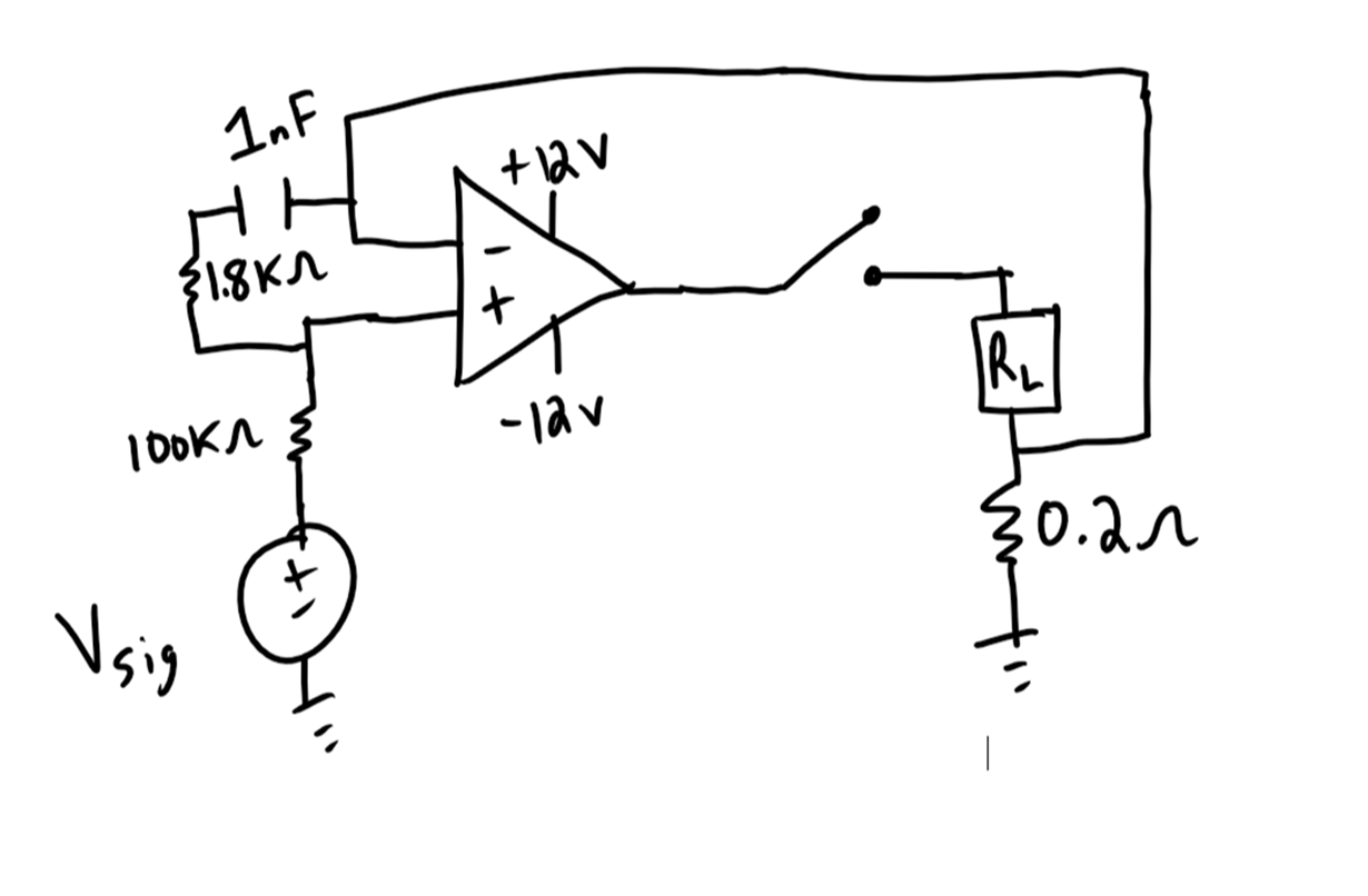
    Thank you for that helpful information. Attached is the customer schematic provided. Does this help give you an idea as to the instability?

    cid:image001.png@01D428A9.C53EAC70

    Additional information:

    Above is a drawing of a section of the circuit which currently uses the LM675T. The op amp is attached to heat sink and dead bugged into the proper nodes on a vector board. Vsig is a sinusoid which will go as high as +/-0.5V and up to 1Mhz. If Voffset = 0, the crossover “hiccup” occurs, the hiccup is about 2 us. As the frequency is increased, it becomes more noticeable and the sinusoid becomes “less pure”. Frequency does not seem to alter the 2us crossover time. If DC offset (positive or negative) is added enough to where the AC signal doesn’t cross 0, the sinusoid looks great, no visible difference between the signal and the LM685T output. If increased up to 1.5-2A with a DC offset so there is no 0 crossing, and up to 200kHz and there isn’t any noticeable distortion in the output. Looking for an op amp, which has a minimal crossover time so up to 20Khz (more comfortable with 50-200kHZ max) can be achieved, < 1% purity error in the sin wave output.


    Interesting instability, if a DMM is wired in series with the 1 ohm resistor load to measure the current, the LM675T seems to go nuts and gives a 2A DC output and gradually decreases, it also shows large amounts of noise added to the Vsig +in line. This behavior is the same whether the cap and resistor connector -in or +in are present or not. This behavior did not happen when OPA544 was used. This seems to be repeatable. The OPA544 does have about a 10us crossover hiccup though.


  • Claire

    This appears to be a duplicate conversation to this thread:
    e2e.ti.com/.../713499

    I'm going to close this duplicate thread...

    Thanks
    Dennis