A related question is a question created from another question. When the related question is created, it will be automatically linked to the original question.
If you have a related question, please click the "Ask a related question" button in the top right corner. The newly created question will be automatically linked to this question.
Thanks for reaching out on our forum. I believe that if you are monitoring the current through an inverter, a negative differential voltage would be from back EMF. Each inductor will want to maintain the current that runs through it and will experience a slow decay from whatever max value that was passed through it.
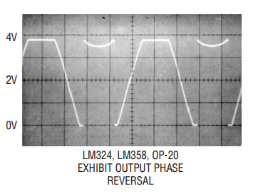
Phase reversal corresponds to change in the order of the phases. In the above diagram waveform B lags A by 120ᵒ and C lags B by 120ᵒ. In phase refersal A would lag B by 120ᵒ and C would lag A by 120ᵒ.
Sorry I misunderstood your first post. This is a unidirectional device and therefore it will only measure current when IN+ is at a higher potential than IN-. Despite it only functioning for forward current, the device can survive reverse current, with absolute max for (VIN+) – (VIN–) = -18V. If you want to measure current in both directions, you need to search for bidirectional devices on ti.com.
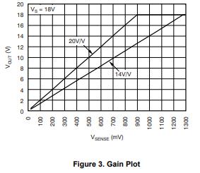
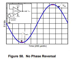
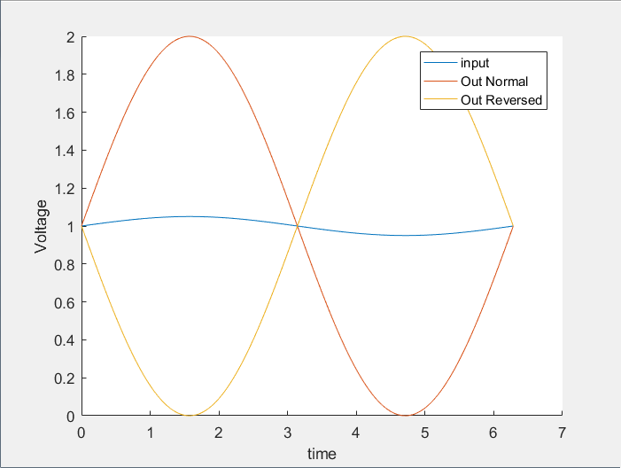
I presume that your meaning of phase reversal is like the diagram below. If not, you will need to provide a diagram of a normal phase versus a reversed phase. If your meaning matches the diagram below, then this device will not invert the output as long as you are operating within the bandwidth of the part. There will be some delay though in how quick the device will follow the input. If you provide a step input into the device, you can use the slew rate specification to determine how long it will take for the output to catch-up with the input. Alternatively if you look at the Gain plot in the datasheet, the device has a little over a 20dB drop per decade, which would indicate that there is a second pole much higher in frequency. So if your signal is in the 10MHz range then there might be a phase reversal. However, your output signal will likely be extremely attenuated at that point.
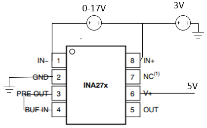
Our device output should not rise above ground if the current is reversed and I did a test to confirm. My setup was as below and the output stayed at 0V despite the differential across IN+ and IN- being increased while the polarity was reversed.