This thread has been locked.

If you have a related question, please click the "Ask a related question" button in the top right corner. The newly created question will be automatically linked to this question.

OPA2376: Example board layout of YZD package

Part Number: OPA2376
Other Parts Discussed in Thread: TPS62301,

Hi,

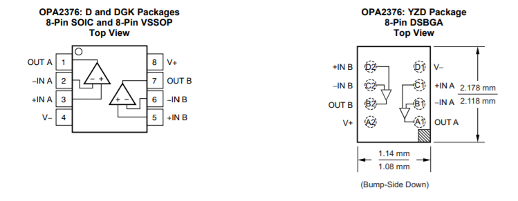
The customer consider to develop test board with OPA2376AIYZD. They'd like to refer the example board layout of YZD package but it's not included in datasheet. So can you share or prepare the example board layout of YZD package?

Best Regards,

Satoshi / Japan Disty

  • Satoshi-san,

    I have searched all of our available resources and have not found a OPA2376AIYZD PC board example. The only information I found for the package is the DSGBA CAD/CAE symbol:

    www.ti.com/.../pinout-quality

    I will continue to look for an example, and will post it if I find something.

    Regards, Thomas
    Precision Amplifiers Applications Engineering
  • Hi Thomas,

    Thank you for your support. Today I found that TPS62301 has also YZD package and the Gerber file of EVM that use YZD package is available. Do you think this Gerber file should be PC board example for OPA2376AIYZD?

    www.ti.com/.../toolssoftware

    Best Regards,
    Satoshi
  • Hi Satoshi,

    Other than the fact that the TPS62301 is available in the same size YZD package as the OPA2376, I am not really sure how the Gerber files would be of much use. Certainly the functions of the two devices are completely different and they require different components and connections. You might be able to use the ball grid pad arrangement information from the TPS62301 Gerber file, but that is about all they have in common.

    I think that the CAD/CAE information for the OPA2376YZD package would provide what is needed with regards to the ball grid pad layout. You would then configure the gain resistors, bypass capacitors, etc. around the outside perimeter of the OPA2376YZD package - just as if you were using one of the larger packages such as the 8-pin VSSOP, or SOIC.

    You will note if you rotate the YZD package shown below by 180 degrees that all the pin functions are in the same positions as they are for the two larger packages. If you can layout a PC board design for the larger packages; then it should be almost identical for the YZD device, except with tighter spacing.

    Regards, Thomas

    Precision Amplifiers Applications Engineering

  • Hi Thomas,

    Thank you for your comment. At this time the customer would like to refer only ball grid pad arrangement information, so it should be OK if its information of TPS62301 Gerber file can be referred.

    Best Regards,
    Satoshi / Japan Disty