This thread has been locked.

If you have a related question, please click the "Ask a related question" button in the top right corner. The newly created question will be automatically linked to this question.

XTR111: XTR111 not working as expected

Part Number: XTR111
Other Parts Discussed in Thread: LM158, OPT101, LM358

Dear All,

I have designed ckt. of XTR111 for following configurations

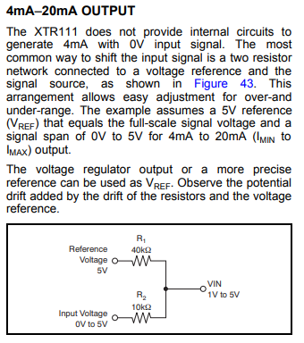
Input voltage range is 0v to 10v , So I have selected RSET = 4.99k. And I want output voltage 4mA to 20mA. To achieve 4mA , voltage divider used between Vin and REGF pin.

Reference voltage is 10v. 

Issues

1) Not getting output current 4mA for 0v input.

2) Output current any random value and sometime above 36mA.

Schematic of XTR111, Please check design and respond ASAP.

Regards,

Prashant

  • Hi Prashant,

    REGF can only source current but not sink. So, if your input signal exceeds the potential at REGF, you get a problem.

    Where is your input signal referenced to?

    Kai
  • Hi kai,

    1) According to datasheet if i want 4mA output, then I need to add resistor divider (my case R31 and R25) to provide 2V input signal to XTR while actual signal is 0v.

    Why to 2V because my input signal voltage range is 0V to 10V. So by referring fig.43 in datasheet. I have calculated R31 and R25 for 2V to 10V Input signal.

    2) My input signal is from OPT101 through LM158 having same ground of XTR111.

    Signal Range 0V to 10V.

    Please reply ASAP.

    Regards,

    Prashant

  • Hi Prashant,

    is the OPT101 and the LM158 also powered by the REGF pin?

    Kai
  • Hi Kai,
    Thanks for for instant reply,

    No , OPT101 and LM158 powered by System supply which is 15V common for OPT, LM, and XTR VSP pin.

    Prashant
  • Hi Prashant,

    that can be a problem. Usually, it's expected that all the input circutry of XTR111 is powered by the REGF pin. Then it's impossible to exceed the voltage at the REGF pin by any input voltage. But in your case, when your 0...10V input signal is derived from a 15V supply, you can easily exceed the voltage at the REGF pin. And this is not good!

    Have you measured your 0...10V input signal with a DVM? I guess that you can exceed the voltage at REGF pin, right?

    Kai

  • Hi Kai,

    Yes I know input ckt. of XTR111 should be powered by REGF PIN. But in my case I have input (0v to 10v) from other side. So I have to give as it is.
    So my question is if I do not use REGF regulating voltage then XTR111 will work??? And what will be the output of XTR111 for 0V and 10V input.?? (For a moment forget about R31 and R25 which is provision to provide 2V input while signal voltage is 0V).

    Prashant
  • Hi Prashant,

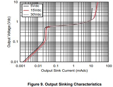
    It is not absolutely necessary to power the input circuitry off of the REGF pin, but as Kai mentioned this does guarantee that you wont exceed the REGF voltage. When you apply 10V at the input this could cause an issue with the regulator. At the low end, when your input is 0V then the LM158 must sink 10V/5.9k = 1.7mA. If you look in the datasheet for the LM158 however, according to figure 9 it cannot sink that much current and maintain a near zero output. This may be why you are not seeing a 4mA output.

  • Hi all,

    Thanks for your valuable reply, 

    Please provide me any suggestion so that I can generate 4mA at output of XTR111 for a given voltage range. Any other way to generate 2V signal at Vin for a 0V input signal.

    Prashant

  • Hi All,
    Recently I have tested ckt. again by removing R30, R25 And also short REGF and REGS pins. But still getting 32mA stable current for 0V and 13V. For this case I expect output 0mA to 20mA.

    And I am using Q3 = BSP170P as a P channel MOSFET.


    Prashant
  • Hi Prashant,

    what Zak wanted to tell you was that you should increase R25 and R31, so that the LM358 must not sink so much current.

    Divide and conquer! Make small steps and check every single step. Let's go back to the circuit you showed us first. Disconnect everything which is not shown in your schematic. I mean all this OPT101 and LM358 stuff. Disconnect it. Then connect the right end of R25 to GND1. Also connect a 100R resistor across R8. What voltage can you measure across this 100R resistor? 0.4V?

    Now connect the right end of R25 to the REGF pin. What voltage can you measure across the 100R resistor now? 2V?

    Kai
  • Hi Kai,
    Thanks for your reply,
    Now i have understand what Zak wanted to correct, I will increase R25 and R31 values and observe the output. And i will update soon.
    But i do not understand second point you mentioned above that 100R across R8. Where is R8 ??

    Prashant
  • Sorry, a typo. Meant D8...

    Kai
  • Hi Kai And TI,
    Thanks for your help, Now I am getting exact 4mA at the output. After adding LM158 also reading are stable.

    Thank you so much!!
    Prashant
  • Hi Prashant,

    what was the mistake?

    Kai
  • Hi kai,
    Sorry for late reply, problem was of not having proper Resistance value of R25 and R31. Now I have increases it to R25 = 82K and R31 = 330k, but ratio is same. And output is exact 4mA while earlier it was around 5mA.

    Prashant