This thread has been locked.

If you have a related question, please click the "Ask a related question" button in the top right corner. The newly created question will be automatically linked to this question.

OPA170-Q1: discrete solution to replace LM1815

Part Number: OPA170-Q1
Other Parts Discussed in Thread: LM1815, OPA170, OPA191, LM2902

Hi team,

my customer is looking for a automotive discrete solution to achieve same function as LM1815, would you please help to provide a solution? is OPA170-Q1 suitable to use? Thanks.

www.ti.com/.../lm1815

Kevin

  • Hi Kevin,

    but both chips are totally different. The OPA170 does not contain a monoflop. e.g.

    Why is the costumer interested in a discrete solution?

    Kai
  • Hi Kevin,

    The OPA170 might be able to work as the amplifier portions of the product you referenced, but there is much more going on in the circuit. Let us know what specific functionality with amplifiers the customer is requiring and we can provide some more direct advice.

    Best,
    Paul
  • Hi kai,

    This is because LM1815 do not have automotive qualified version. so we want to try to use automotive qualified device to build a discrete solution.

    Kevin
  • Hi Paul,

    the input siganl is a sinusoidal wave, the minimum input amplitude is +/-233mV, the maximum input amplitude is +/- 180V, frequency is below 1kHz. Customer need a solution to process the input signal, to get a PWM signal that have the same frequency as the input siganl. then, the PWM signal is connent to a MCU TIM input (timer) and MCU calculate the frequency.

    would you please help to suggest a solution? Thanks.

    Kevin
  • We have a circuit cookbook that covers a PWM generator - it doesn't quite meet your needs, but is this the type of waveform the customer is looking for? www.ti.com/.../sboa212.pdf

    Otherwise, it sounds like the customer is really looking for a type of zero-crossing detector. The most difficult requirement is the wide input voltage range, but I think with the creative use of input diodes, you could limit the input voltage and create the waveform you're looking for. I think a comparator would be best for this application though.

    Let me know what type of PWM output your customer is looking for.

    -Paul
  • Hi Paul,

    we think it should be working as a zero-crossing detector. would you please share your idea about how to use input diode to handle the wide input voltage range? we think it should like have buffer amplifier to handle this wide input voltage range and then, the amplifier output go to comparator, right?

    Kevin

  • Hi Kevin,

    the range of input signal is huge, as if the signal is coming from an inductive sensor. Is this right?

    Kai
  • Hi Kai,

    Yes, Variable reluctance (VR) sensors, also known as mag (magnetic) sensors are
    built with a wire wound around a permanent magnet (pole) similar to a solenoid or DC
    motor.

    Kevin
  • Hi Kevin,

    can you give us a datasheet of this sensor?

    Kai
  • Hi Kai,

    customer didn't get sensor datasheet from their end customer, they only got sensor output signal description: the input siganl is a sinusoidal wave, the minimum input amplitude is +/-233mV, the maximum input amplitude is +/- 180V, frequency is below 1kHz.

    Kevin
  • Hi Kevin,

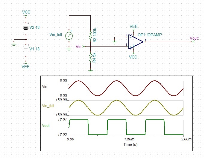
    I think your best option is to take a high voltage op-amp like the LM2902 or OPA191 and use a voltage divider to reduce the input voltage by 20 and feed the divided signal into the op-amp in comparator mode. You'll get a square wave output that you can use as your zero-crossing detector. It will be best to choose a device that has a wide supply range and a fairly low offset. Also, the device you choose cannot have back to back input diodes for proper function.

    Something like this:

    Best,

    Paul