Because of the holidays, TI E2E™ design support forum responses will be delayed from Dec. 25 through Jan. 2. Thank you for your patience.

This thread has been locked.

If you have a related question, please click the "Ask a related question" button in the top right corner. The newly created question will be automatically linked to this question.

LM2904: LM2904 for current sensing

Part Number: LM2904

Hi team,

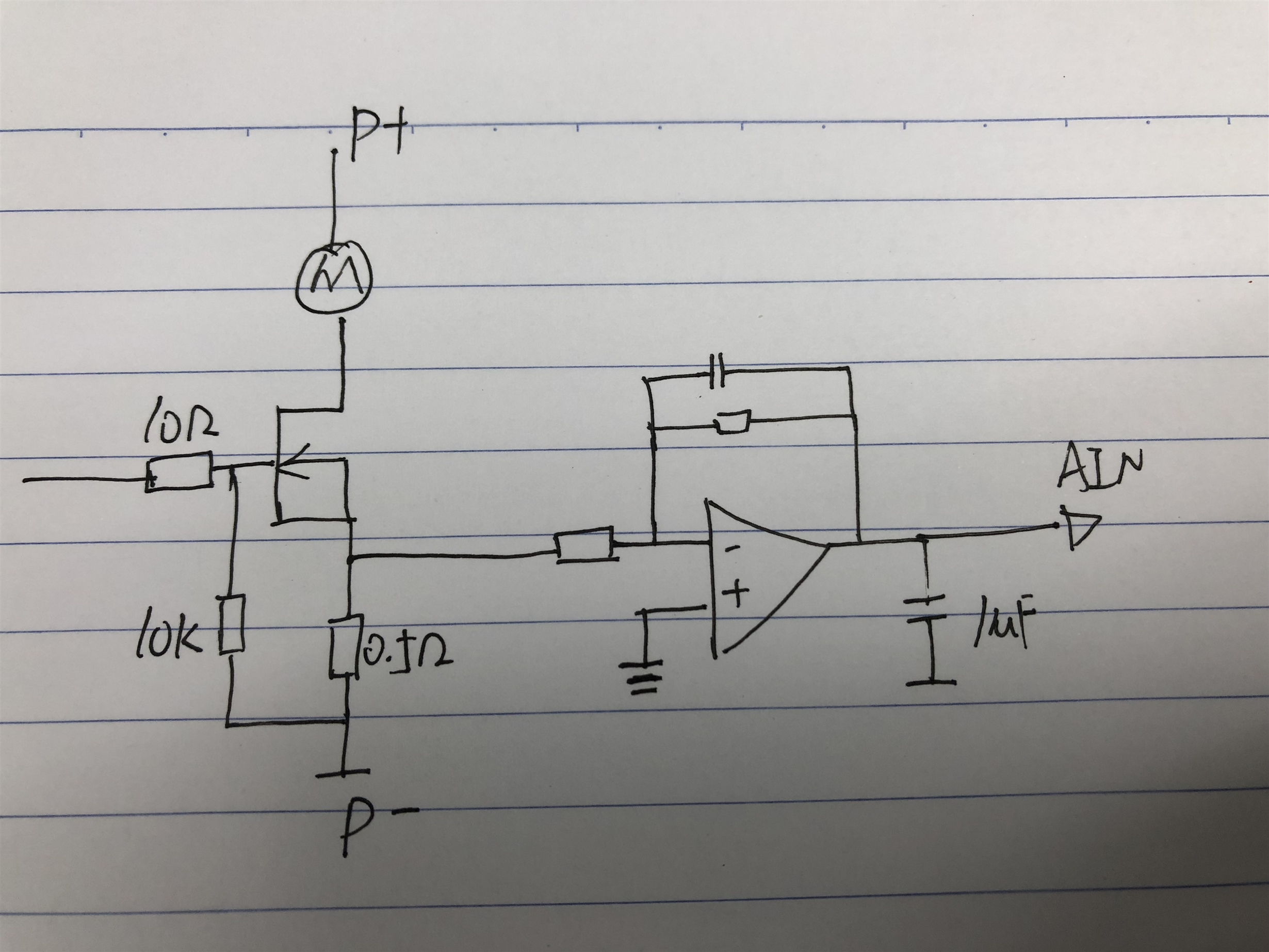
My customer is using LM2904 to detect the motor current for the cordless vacuum cleaners application. As picture shown as below, the MOS is either on or off for a long period. Customer want to test the average current from AIN PIN(from a simple MCU), but the integrated AD is very slow(120k) and only have 8 bit. So they add a 10uF capacitor for the output of amplifier in order to get the average current of the motor.

Question is using this 10uF cap, I am wondering if this will cause stability problem and the response is very slow.

Do you have any suggestions for this? or a better solution? 

Thanks!

  • Hi James,

    I cannot see a picture...

    Kai
  • Hi James,

    Thanks for your interest in our part. Please upload your schematic  in order for us to assist you with your design.

    In the meantime, please refer to our cookbooks circuits in the current sensing section for design tips.

    www.ti.com/.../slyy137.pdf

    Look forward to hearing from you.

    Regards,

    -Mamadou

  • Hi Kai,

    Sorry that the picture fail to upload in the first time.

    Please check the picture as below, thanks!

  • Hi James,

    why not increasing the feedback capacitance (from the -input to the output) of LM2904?

    Directly connecting a big capacitance from the output of an OPAmp to signal ground is no good idea. This will erode the phase margin and can cause instability. You could insert a resistor of >50R between the output of LM2904 and the 1µ cap. This will isolate the capacitve load from the output and decrease its negative effect on the phase margin.

    Can you show us a complete schematic?

    Kai
  • Hi James,

    In addition to Kai's comments, please refer to this link for general guidelines on common stability issues and things to watch out for in order to prevent potential oscillations at the output of your op amp.

    training.ti.com/ti-precision-labs-op-amps-stability-1

    If you can also add the values of your feedback caps and resistors, it would helps us be more helpful in determining any other potential issues.

    Thanks.

    Regards,

    -Mamadou

  • Hi Kai, Mamadou,

    I've checked with customer and have this complete schematic as below.

    They were trying to use the 1uF cap to filter and get the average current from the motor which is a sine wave current. Because in this cordless vacuum cleaners application, they need to know the current so that they know what is the contact surface, is it a blanket or smooth earth.
    About the average current, they don't need a high accuracy, rough data around the actual value, like 0.9A~1.1A for 1A. This could be enough for them.

    Care Point: quick response; low cost
    Now the question is, they want to know if they can improve the current circuit to get the quick response. Or is there any other solutions?

    Thanks!

  • Hi James,

    the easiest way to do an effective averaging is to use the 150k resistance in the feedback loop and to increase the 100nF cap. The time constant of the averaging is 150k times this capacitance. If you put a cap directly at the output of OPAmp, on the other hand, the output resistance is nearly zero and by this no averaging can be achieved. Apart from this the OPAmp becomes instable and shows ringing or even oscillation.

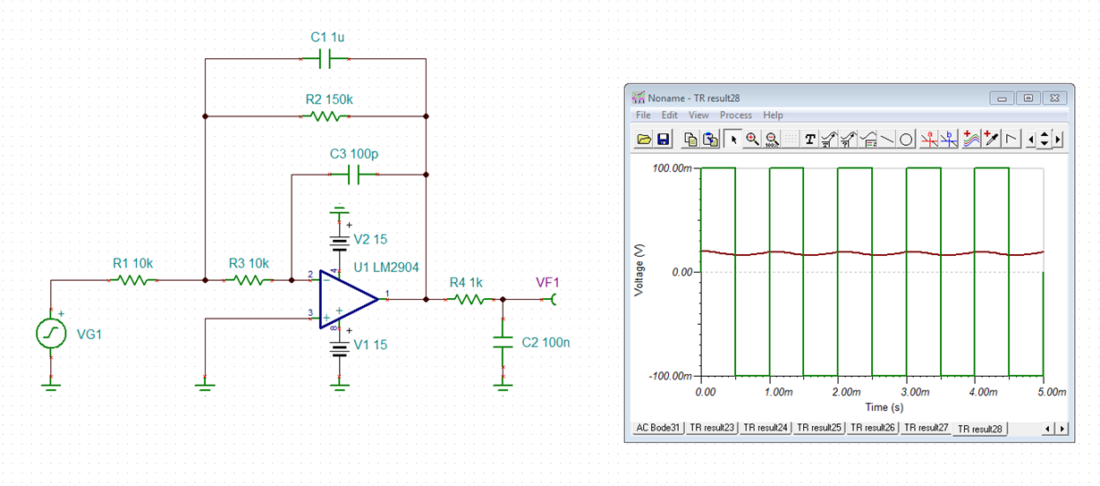
    I would recommend the following circuit:

    R2 and C1 do the averaging. (C1 can be further increased.) C2 helps the following ADC to properly settle to the correct value. R4 isolates the OPAmp's output from the capacitive load of C2 and stabilizes the OPAmp.

    R3 limits the input current of LM2904 and by this protects the OPAmp from damage, if the power supply voltage is suddenly removed and C1 still carries some charge. C3 recovers the phase margin again from the phase lag introduced by R3. This helps to stabilize the OPAmp.

    Kai