This thread has been locked.

If you have a related question, please click the "Ask a related question" button in the top right corner. The newly created question will be automatically linked to this question.

INA219: Server BMC current value abnormal data read

Part Number: INA219


Hi Guys

Our customer is using INA219 as system current sense. They are sensing PCIe Slot Power. they found:  BMC read data shows 2W load when PCIe slot take 0A load;(total 6 pieces at PCIe). And they did some actions:

1. Test Vshunt when PCIe take 0A load. Result: there is no Vshunt when 0A load;

2. They have tried to change the INA219 configuration/calibration register, but the smallest data they can read is still 2W;

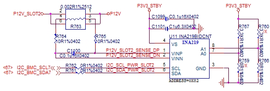
Next it is their schematic, could you help me with the schematic and give some feedback about this? this issue is very urgent. any feedback are appreciated!

Thanks

-Vincent

  • In Spec., there is a Step9/Second Calibration when doing Calibration. There are some following questions:

        1. If we didn’t do Second Calibration, it will cause the reading of Current, Power and actual error,Right?

        2. Do we have to use a tool like the INA219 Test Board to do Step9/Second Calibration?

    The INA219 Test Board:

  • Hello Vincent,
    Thanks for reaching out on the forum. For no load, is your IN- floating, high-z, or ground? When I use the EVM, shorted Vin+=Vin-=GND, before step 9, my power register reads 0W. After step 9, my power register still reads 0W.
    Do you only see incorrect measurements at no load? Have you probed your communication lines to see if the data is getting corrupted?
    What I see in your schematic looks fine. However, what is upstream of the Vin+ and Vin- pins? At no load, is the common mode voltage within the absolute maximum specifications?
    There will always be some degree of error. Lower currents will always have the largest, as there is an offset voltage from the input bias current and CMRR. However, if you do the second calibration at 0A, you should be able to calibrate out this offset. You do not need to use the EVM tool. As long as you have a microcontroller with I2C capability, you can do the same thing as the EVM. You simply need to run the debug mode in the development environment like code composer studio.
  • Thanks Patrick. I will try to re-work by your comments. but as for the last comment, you said: if you do the second calibration at 0A, you should be able to calibrate out this offset. You do not need to use the EVM tool. As long as you have a microcontroller with I2C capability. How to run debug mode in the development environment? do you have some user guides?
    Thanks
    -Vincent
  • Hello Vincent,

    You should ask your customer what microcontroller they are using and reach out to the microcontroller team. They typically have sample code available for various functions on the microcontroller, including i2c communication. If your client is not using a TI microcontroller, I would recommend getting a MSP430 launchpad. However, if you really just want to evaluate the operation of the INA219, I would highly recommend getting the EVM and using an oscilloscope with a decode function or a logic analyzer and probing the SDA and CLK lines. This will help you understand what should be seen versus whatever your client is seeing in their i2c communication exchange.
  • Dear Patrick,

        Thanks for your help and reply!

        Customer recomfirmed that the Vshunt=0V while no loading, but found the sence input(VINP to VINN) exist a ~0.3mV offset voltage.

        We tried to change R764/R765 to 0 omh and the offset voltage disappeared, we will do the accuracy verification later and find if it ok with R764/R765 mount 0 ohm.

        Thanks...

        PS:Update the schematic as below.(Treat R763 pin1/3/5 as one pin and same as pin 2/4/6.)


    So here do you think it is related to the R764 and R765?

  • Hello Vincent,

    We do expect input filter resistors to produce some offset error. This is why we typically recommend that resistors be no larger than 10 ohm and have a small tolerance <=1%. If there are no input filter resistors at all, then the error should be smaller. So if your customer does not need an input filter then I would recommend your customer to remove it.