This thread has been locked.

If you have a related question, please click the "Ask a related question" button in the top right corner. The newly created question will be automatically linked to this question.

TINA/Spice/OPA111: Simulated vs Actual Performance

Part Number: OPA111

Tool/software: TINA-TI or Spice Models

How accurately does the Spice model for the OPA111 represent the real life performance of the part?  I need to know what might be causing differences between our experimental data and the data from simulation.  Are there are any aspects of the OPA111 part not taken into account in the Spice model?

  • Hi Michael,

    there's no Spice model which models all the parameters of an OPAmp. What differencies have you observed? Can you give us more details?

    Kai
  • Hi Michael,

    The OPA111 is a legacy op amp that is not recommended for new design (NRND). It was developed more than 3 decades ago and its Spice simulation model is limited to a few dc, ac and noise parameters. It uses a behavioral model that contains very few transistors so it is a lot less sophisticated than modern op amps. Burr-Brown was using the popular Boyle op amp model during that time and the OPA111 model syntax looks to be that of a Boyle model. There is paper from that era that describes the model:

    www.ti.com/.../sboa027.pdf

    I did some quick checks using the TINA Spice circuit and the voltage offset is et to 2.5 uV, the operating current to 2.5 mA, input bias current is about 14 pA. The open-loop gain-phase results in a unity gain bandwidth of 1.9 MHz. The voltage noise spectral density at 1 kHz is 6.6 nV/rt-Hz, and the 1/f noise characteristics look correct according to the noise graph in the datasheet. The model does include the current noise spectral density and the common-mode and differential input capacitances. It would take more time to determine what else it models, but I don't expect much else.

    Regards, Thomas
    Precision Amplifiers Applications Engineering
  • In the experimental data for our circuit, which includes the OPA111, the gain drops off orders of magnitude earlier than what our simulation of the circuit in spice gives us, so I am trying to find out if there might be any non-idealities which are not represented in the spice model which would account for discrepancy between the spice model of the OPA111 and the real life part.
  • Hi Michael,

    can you show us a schematic?

    Kai
  • Here is an image of the first stage of our preamp, and the graph that shows the gain from the experimental data vs the simulated data.  The high resistances are necessary for the application in which we are using the preamp.  We would like to know if there might be a reason for the early fall off in our experimental setup.

  • Just going to note, we are using LTspice, and the code for the OPA111 is downloaded from TI using the Pspice model.
  • Hi Michael,

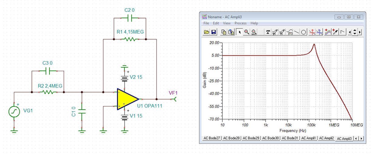
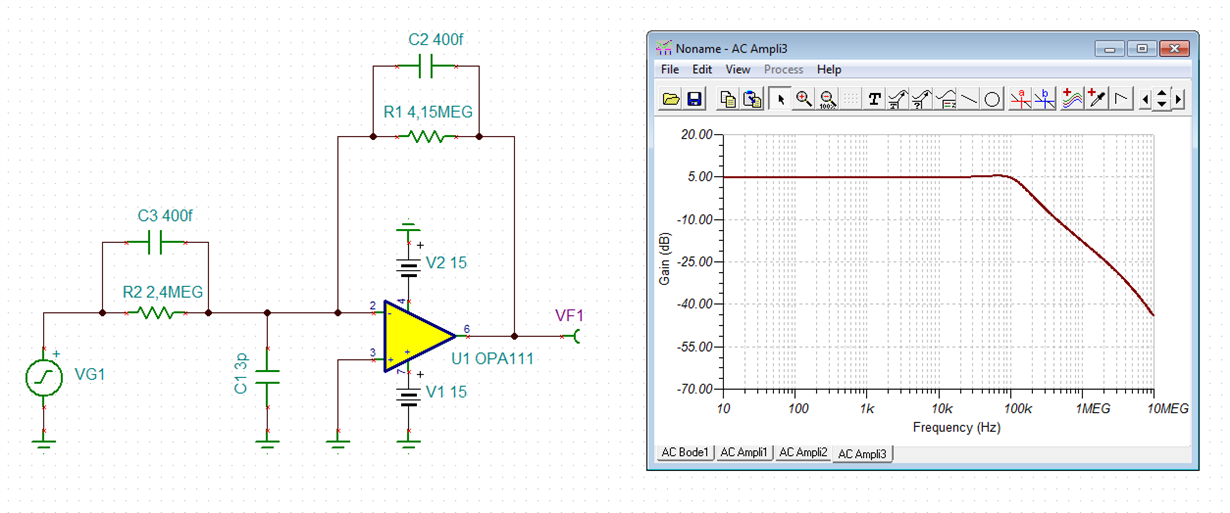
    if you assume perfect resistors and the absence of any stray capacitance, then you will get the following frequency response:

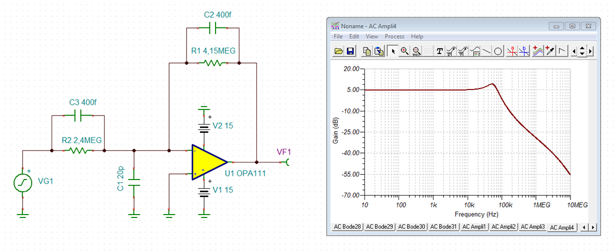
    But if you additionally take into account the parasitic capacitances which each resistor has between its terminals and the stray capacitance at the -input of OPA111 between the wiring and signal ground, you might get the following frequency response:

    Ok, the added capacitances look a bit fabricated, of course. I have varied them by hand until the frequency response showed the same shape as what you have observed in your measurements. But the values make sense and are absolutely plausible.

    One way to reduce the impact of parasitic resistor capacitances (C2 and C3) on the frequency response is to put several resistors in series. And the stray capacitance C1 can only be decreased by directly soldering the resistor terminals of R1 and R2 to the -input of OPA111, by using shortest connections.

    crotty.TSC

    Kai

  • Okay, thank you, this seems to give us an idea of what to look at. We were planning on figuring out how the parasitic capacitance of the resistors affects our circuit anyway.
  • Might I ask why your capacitor C1 is connected straight to ground? and also where dos the value for 20pF come from, because it seems rather high compared to the other values of 0.4pF.

  • Hi Michael,

    I ran an open-loop gain/phase (Aol) plot on the OPA111 simulation model. You can see the results below. The datasheet Aol plots are what would have been measured on a test setup, while the simulation Aol model was built to mimic that result closely. The model exhibits an ideal, dominant pole roll off with a pole at approximately 1 Hz.

    The datasheet phase plot indicates there are some additional pole/zero influences between 100 kHz and 1 MHz, but the gain appears to roll off at a constant -20 dB/dec. The phase deviation is maybe 10 degrees so the fact that the simulation model doesn't capture this characteristic likely won't have much effect on the end use result.

    As mentioned earlier, the OPA111 is not recommended for new designs. There are no plans to develop a modern simulation model for the product. If you would like to experience how much different modern SPICE-based op amp models are compared to a legacy Boyle model, try one of the newer precision op amps models; OPA192, OPA187, OPA202, etc. Their ac/transient behaviors are accurately modeled and they include the important complex open-loop output impedance (Zo) characteristics needed for accurate transient and stability analyses. 

    Regards, Thomas

    Precision Amplifiers Applications Engineering

  • Hi Michael,

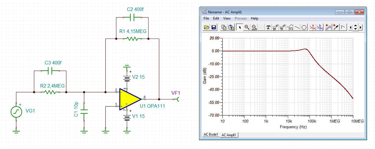
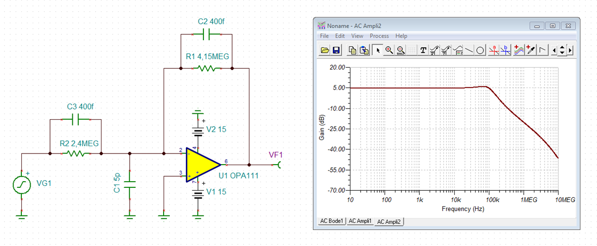
    as I already said the values are a bit fabricated. I just wanted to catch your peak in the frequency response which sits between 10kHz and 100kHz. But even with a much smaller stray capacitance between the -input of OPAmp and signal ground a peak in the frequency reponse can be seen. But then the peak will wander to higher frequencies. (I had attached the TINA-TI file so that you could do your own simulations.)

    Don't take these simulations too literally. Important is not where exactly the peak in the frequency response can be seen and how high it is. Important is the fact that there IS a peak and that it comes from parasitic capacitances and stray capacitances which must not be neglected.

    Where the stray capacitance from the -input to signal ground comes from? Connecting the feedback resistors via long wires to the -input of OPAmp can cause lots of stray capacitance. Using breadboards can result in considerable strip-to-strip capacitances. Sometimes a metal plate can sit directly under the strips which can additionally increase the stray capacitance.

    Kai

  • Michael

    We haven't heard back from you so we assume this answered your questions. If you need additional help just post another reply below.

    Thanks
    Dennis