This thread has been locked.

If you have a related question, please click the "Ask a related question" button in the top right corner. The newly created question will be automatically linked to this question.

INA199: Current Leaking through the sensor

Part Number: INA199

Hi,

I am using INA199B2 bidirectional current sensor for my project.

I powered the system with 12V battery. I had also a voltage regulator stepping voltage down from 12V to 5V which was used as a power supply for my INA199B2 chips.

After energizing the circuit I find out that the voltage supply port of INAB2 is exactly the same as my battery voltage.

I had a similar problem before when I used INA100A2. I was told that version B should be enough to solve my problems. 

How can I fix it? 

Best Regards,

Bartosz

  • Hello Bartosz,

    Thanks for using our forum. Is the INA199 the only device supplied by the 5V regulator output? Do you have split ground planes? If you have split ground planes, it is possible that the device can experience unanticipated operating conditions that exceed device specifications. Have you probed to see if the input pins ever pull beneath the device ground?

    Could you provide a basic schematic of you current shunt monitor setup? This will help us better understand your system and we may be able to determine what is causing 12V to appear on your device supply.
  • Hi Patrick,

    Thanks a lot for a quick reply.

    INA199 is the only device supplied by 5V in my system so far.

    Could you please tell me what exactly do you mean by split ground planes?

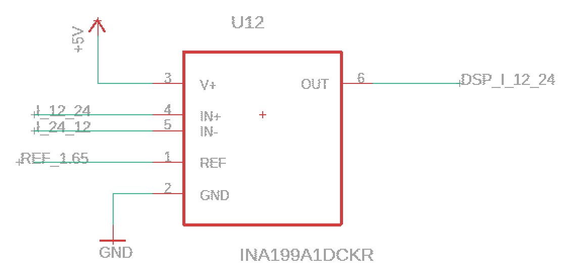
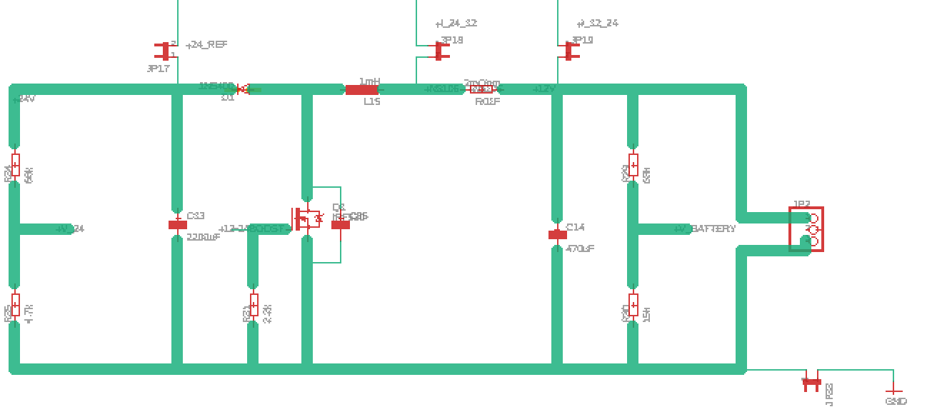
    I've attached a bit of the schematic which I am currently using in the experiment.

    I am using different net classes and had to install jumpers to separate them. On my board jumpers act in fact as short circuits. Voltage Regulator circuit steps down voltage from 12V to 9V first (you can see 9V battery connected). The second switching regulator steps down further to 5V which is connected to the supply of INA199. Pin representing Ref (is not connected yet at this stage).

    Please let me know if you have any further questions.

    Best Regards,

    Bartosz   

  • Hello Bartosz,

    Thanks for providing that.  Split ground planes typically refer to the practice where the designer has a ground plane for analog parts and a separate ground for digital parts with a small trace connecting the two planes.  There are also tricks people will try to play in high voltage applications where they have the device ground disconnected from the load ground because they have are trying to do a high-side measurement in which the common mode is higher than the device specification.  Then there are those who have multiply supplies and try to get by without having a common ground because it is difficult or inconvenient to connect them all.  If you do have separate ground planes for your analog and digital ground, I would recommend reading this link or this link.

    With regard to your buck regulators, I did notice something in the schematic that did not quite make sense, perhaps what you built is actually different.  U17 and U10 both appear to be R-78E5.0-0.5 which if provided a proper input should output 5V.  I suspect that if U17 actually is a R-78E5.0-0.5 and not a R-78E9.0-0.5, that could cause an issue.

    As for C25, do you have that close to the INA199A1 supply pin (a few mm to a cm)?

    As for circuit on the bottom, I presume you are measuring the ripple through your inductor for a boost circuit.  What is your duty cycle and switching period?  

    If your REF pin is floating, that can definitely cause issues.  I would recommend connecting it to the 1.65V rail or at least grounding it for your preliminary measurements.

  • Hi Patrick,

    Thanks a lot for that. 

    I am actually using two different switching regulators. These are  R-78E9.0-0.5 and R-78E5.0-0.5. 

    I tested a new circuit with REF grounded and it seems to be working fine so far. I have 5V supplying sensors. I am regulating my boost converter to give me 24V. There are some voltage spikes exceeding 26V though. Perhaps this is a problem. I am going to run more experiments and will contact you in case of problems. 

    Thanks a lot for support.

    Bartosz

  • Hello Bartosz,

    If your inputs to the INA199 are seeing voltage spikes exceeding 26V, you should install some zener diodes or tvs diodes to limit those spikes to within the device specifications to avoid either an immediate device failure or even a slow degradation of device performance and eventual failure.
  • Hello Bartosz,

    I have not heard from you in a while. I presume you were able to get your system up and running without any further issues. As such I am going to close this thread. However, if you need further support, please respond below or start a new thread.