This thread has been locked.

If you have a related question, please click the "Ask a related question" button in the top right corner. The newly created question will be automatically linked to this question.

LMP91000: LMP9100: SIGNAL DROP

Part Number: LMP91000
Other Parts Discussed in Thread: TCA9548A

Dear all,

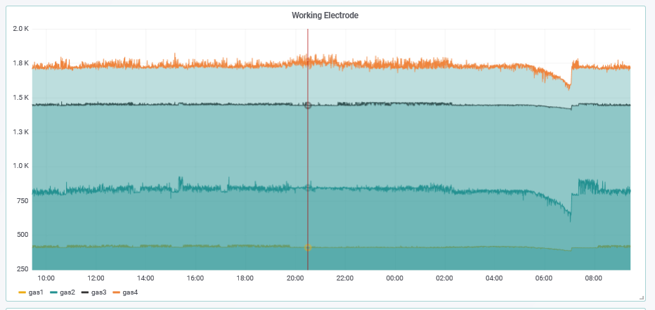
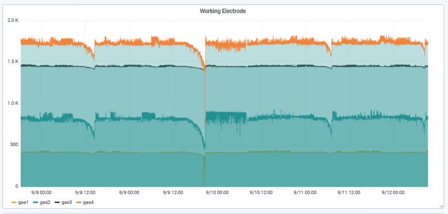
I'm testing my own electronic designed for 3 and 4 electrodes sensors. I was reviewing the last 4 days of a OX-A431 Alphasense sensors, and it present a signal drop that tough four hours, and then the device was reset and the signal come back to the original value. It happened for both Working and Auxiliary electrodes. 

I had 3 more sensors (of the Alphasense A4 series)  connected to the same device, and its present the same signal drop at the Working Electrode (not at the Auxiliary) at the same time. This happened two times.

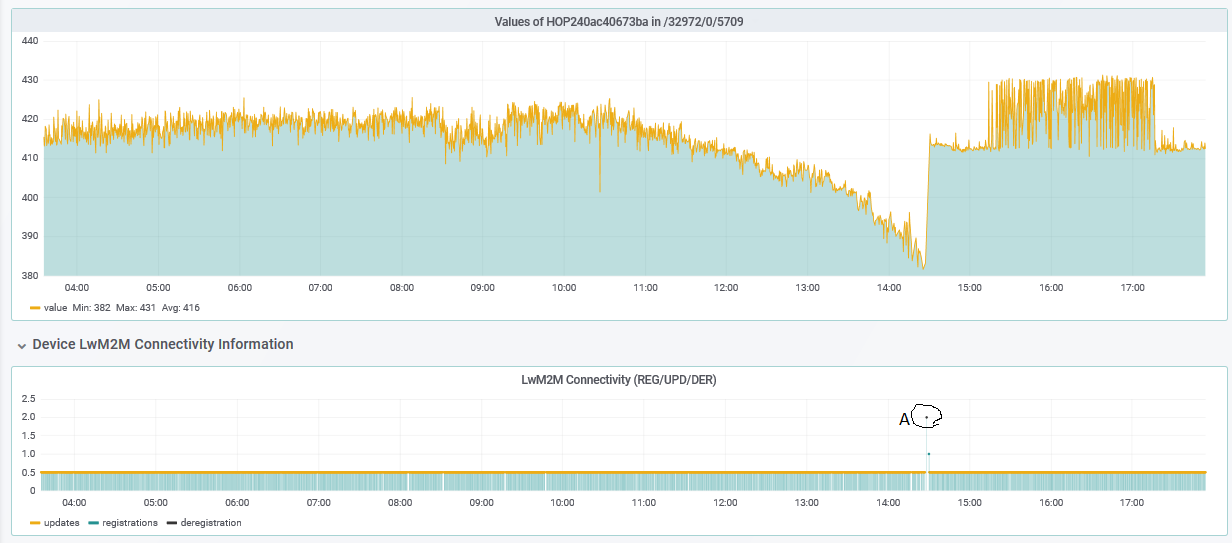
The LMP9100 works in 3-lead amperometric cell, and goes to standby between each read. Could it be that the sensor goes to sleep mode and when was reset it went to 3-lead amperometric cell?

The point A is when was reset.

Thanks in deep.

  • Hello Roque,

    When you say you had 3 more sensors connected to the same device, do you mean that you replaced the device 3 times, or they are all connected at the same time? Also, when you say that it happened 2 times, do you mean that the output dropped over 4 hours twice with the same sensor, or with two different sensors?

    Also, what are you writing to the OP_MODE register? It will not go into sleep mode unless 000 is written to the OP_MODE register.

    Thanks and Regards,
    Audrey
  • What I mean is that I have 3 board with LMP9100 each one with a sensor, all these connected to a one principal board which acts as an acquisition board, so they are all connected at the same time. The signal drop happened 2 times in all the sensors. In other words, the signal drop in all the sensors, at it happend again next day.
  • Hello Roque,

    Can you make some voltage (VDD, VREF, VOUT) and signal (SCL, SDA) measurements during the period when the signal is reducing and also after you reset the LMP91000 and it returns to the normal level? Also, could you share how your registers are set up?

    Thanks,
    Audrey
  • By now, I can not take this measures.

    Note: in all this sensor I'm using external resistor for R_TIA

    This is the initial configuration, afterwards I change the values for Rload and INT_Zero depending on the sensor:


            /* Default values for LMP*/
            concentration_instance->tian_gain = 0;
            concentration_instance->tian_rload = 1;
            concentration_instance->refcn_intz = 0;
            concentration_instance->refcn_bias_pos = 0;
            concentration_instance->refcn_bias_n = 0;

    Where:

    #define LMP_TIACN_REGISTER        0x10

    #define LMP_TIACN_GAIN_STARTBIT        2
    #define LMP_TIACN_GAIN_ENDBIT        4
    #define LMP_TIACN_GAIN_EXT        0x00
    #define LMP_TIACN_GAIN_2_75        0x01
    #define LMP_TIACN_GAIN_3_5        0x02
    #define LMP_TIACN_GAIN_7        0x03
    #define LMP_TIACN_GAIN_14        0x04
    #define LMP_TIACN_GAIN_35        0x05
    #define LMP_TIACN_GAIN_120        0x06
    #define LMP_TIACN_GAIN_350        0x07

    #define LMP_TIACN_RLOAD_STARTBIT    0
    #define LMP_TIACN_RLOAD_ENDBIT        1
    #define LMP_TIACN_RLOAD_10        0x00
    #define LMP_TIACN_RLOAD_33        0x01
    #define LMP_TIACN_RLOAD_50        0x02
    #define LMP_TIACN_RLOAD_100        0x03

    //----------------------------------//
    #define LMP_REFCN_REGISTER        0x11

    #define LMP_REFCN_REFS_STARTBIT    7
    #define LMP_REFCN_REFS_ENDBIT    7
    #define LMP_REFCN_REFS_INT        0X00
    #define LMP_REFCN_REFS_EXT        0x01

    #define LMP_REFCN_INTZ_STARTBIT    5
    #define LMP_REFCN_INTZ_ENDBIT    6
    #define LMP_REFCN_INTZ_20        0X00
    #define LMP_REFCN_INTZ_50        0X01
    #define LMP_REFCN_INTZ_67        0X02
    #define LMP_REFCN_INTZ_CIRC        0X03


    #define LMP_REFCN_BIASS_STARTBIT    4
    #define LMP_REFCN_BIASS_ENDBIT        4
    #define LMP_REFCN_BIASS_NEG        0X00
    #define LMP_REFCN_BIASS_POS        0X01


    #define LMP_REFCN_BIAS_STARTBIT    0
    #define LMP_REFCN_BIAS_ENDBIT    3
    #define LMP_REFCN_BIAS_0        0X00
    #define LMP_REFCN_BIAS_1        0X01
    #define LMP_REFCN_BIAS_2        0X02
    #define LMP_REFCN_BIAS_4        0X03
    #define LMP_REFCN_BIAS_6        0X04
    #define LMP_REFCN_BIAS_8        0X05
    #define LMP_REFCN_BIAS_10        0X06
    #define LMP_REFCN_BIAS_12        0X07
    #define LMP_REFCN_BIAS_14        0X08
    #define LMP_REFCN_BIAS_16        0X09
    #define LMP_REFCN_BIAS_18        0X0A
    #define LMP_REFCN_BIAS_20        0X0B
    #define LMP_REFCN_BIAS_22        0X0C
    #define LMP_REFCN_BIAS_24        0X0D
    //----------------------------------//

    #define LMP_MODECN_REGISTER        0x12

    #define LMP_MODECN_FET_STARTBIT    7
    #define LMP_MODECN_FET_ENDBIT    7
    #define LMP_MODECN_FET_DIS        0x00
    #define LMP_MODECN_FET_ENA        0x01


    #define LMP_MODECN_OPM_STARTBIT    0
    #define LMP_MODECN_OPM_ENDBIT    2
    #define LMP_MODECN_OPM_DSLEEP    0x00
    #define LMP_MODECN_OPM_2ELEC    0x01
    #define LMP_MODECN_OPM_STANDB    0x02
    #define LMP_MODECN_OPM_3ELEC    0x03
    #define LMP_MODECN_OPM_TEMP1    0x06
    #define LMP_MODECN_OPM_TEMP2    0x07

    And in this way change to "3 lead amperimetric" mode to make the measure, and afterwards goes to standby:

    float MCP3423::readAnalogValueOSMode1XPGA(uint8_t socket_Number, electrode_Enum electrode){

        // Use TCA to select the I2C channel to communicate with the MCP3423/LMP91000 on the gas socket number we want to read
        if (!TCA9548A::get_TCA9548A()->TCA9548A_Change_I2C_Channel(socket_Number)) {
            ESP_LOGE(tagg, "Switch I2C Channel via TCA9548A failed!");
            return 0.0;
        }

        // Introduce a delay to let TCA correctly switch the channel
        vTaskDelay( 10 / portTICK_PERIOD_MS);

        // Configure LMP91000 to take the measure (pag 19 of datasheet) [ //INFO: On first version (vicente) the LMP91000 was enabled only if reading working electrode? ]
        if(!LMP91000::get_LMP91000()->SetMODECN_3leadamperimetric(socket_Number)){
            ESP_LOGE(tagg, "Set LMP91000 as 3 lead amperimetric failed!");
            return 0.0;
        }

        /* Configure MCP3423 to fire a measurement on the desired electrode channel */
        if (!fire_channel_read(electrode)) {
            ESP_LOGE(tagg, "Fire ADC measurement via MCP3423 failed!");
            return 0.0;
        }

        /* Read the result of the measurement carried out by the MCP3423 */
        float read_result = 0;
        if (!read_channel_result(&read_result)){
            ESP_LOGE(tagg, "Read ADC measurement via MCP3423 failed!");
            return 0.0;
        }

        /* Configure LMP on stand by mode */
        if(!LMP91000::get_LMP91000()->SetMODECN_standby()){
            ESP_LOGE(tagg, "Set LMP91000 as standby failed!");
            return 0.0;
        }

        /* Return the obtained result from MCP3423 */
        return read_result;

    }


    Yesterday this happened again, here a plot with the 4 sensors:


  • Roque,

    Could you please share your schematic and show what external resistors you are using and how you interface your sensors with the LMP91000 device?

    Where in your circuit are you measuring the output waveforms you have shared? What are the units of the y-axis?

    Additionally, are you using the temperature sensing mode of the sensor? If so, notice that the output of the gas sensor will be at pin C2 if TIA is ON if set in temperature sensing mode, because the temp sensor output will be at VOUT.

    Thanks,

    Audrey
  • Hello,

    1.- I am using the same circuit that in the following picture, with Vout and Auxiliary_chanel directly connected with the MCP3423 ADC. The LMP9100 use an external estable reference of 2.048 V.

    2.- It use external resistor with a value similar to the internal RTIA, and a +-1% of tolerance. (each sensor use a different resistor). All resistor with a value below 350 K. 

    3- I measure the output with the MCP3423

    4.- The units are mV in the vertial axy, and Hours in the horizontal.

    5.- I not use the temperature sensing mode.

    6.- Rload = 33 ohm

    Note: I discard that it be a problem of the ADC and external reference due to, 3 sensors have 3 electrodes and one 4 electrodes. The signal Auxiliary Electrode of the 3 electrode sensors is always constant, while on the other hand in the 4 electrode sensor the axuliary electrode present the same problem that the Working, so the reference and ADC is OK. I assume that the problem is related with the potentiostat circuit or with the mosfet between working and reference.

    Thanks in deep for your help!

  • Hi Roque,

    Which signal input pin are you using to plot the signals you showed? Is it from the VOUT, Gas concentration, or Auxiliary channel pin? And if you are not using the temperature sensing feature, then I'd imagine VOUT and Gas concentration should be the same.

    Also, do all of your sensors share the same MSP430?

    It would help very much if you were to capture the output of VOUT and/or Gas concentrator pins directly out of the LMP91000 using an oscilloscope to help me see if the LMP91000 is the issue. If you could determine how often/when the dip in signal occurs, you could measure during that time. Or if you notice the dip again, as it seems to happen multiple times, you could begin measuring the output at that point and after you reset the circuit.

    Finally, why do you say that the 3-electrode sensors all have constant output? It looks like all 4 sensors have a dip in the signal from the image you provided before. The 3-electrode sensor should not have any auxiliary connection. So it looks like the problem has to do with the common connection of all four sensors, as opposed to the LMP.

    Regards,

    Audrey
  • Hello Audrey,

    1.- I am using VOUT to plot the signals.

    2.- I have 4 boards, one for each sensor with its own LMP9100 and MCP3423.

    3.- It is difficult to connect the oscilloscope to the board, but I will try.

    4.- What I mean, if that my board read the both Working and Auxiliary electrode, obviously in 3 electrodes sensors, the Auxiliary electrode doesn't have any connection, and the signal that i measure with the ADC in Auxiliary_channel is Ok, with a value similar to INT_ZERO, due to the connection in C1. In the sensor that i have connected with 4 electrodes, the output in the auxiliary electrode have the same signal drop that the Working.

    Other question, the LMP9100 datasheet in page 19 said:

    "In the standby mode, the TIA is OFF, while the A1 control amplifier is ON. This mode of operation is suggested when the gas detector is not used for short amount of time and a faster warm-up of the gas detector is required"

    How many time you consider "short amount of time"?

    It have happened again..:

    How can I share schematics with you privately?

    The forum is some tedious, due to we are in different time zone, could we chat at some hour?

    Thanks!

  • Hello Roque,

    I would ask that you please provide the oscilloscope measurements for the supply voltage VS and the output VOUT before we look at anything else. Also, could you describe your test conditions? Since it appears the issue happens consistently, you can determine when to begin taking those measurements while it is happening. I sent a private message request so we can continue to discuss via the messenger if you have some private schematics/information you would like to share.

    Thanks,
    Audrey
  • Finally I have found the problem, a transistor wrongly configured cause the problem. Thank you all