This thread has been locked.

If you have a related question, please click the "Ask a related question" button in the top right corner. The newly created question will be automatically linked to this question.

RTOS/OPA857EVM: OPA857EVM

Part Number: OPA857EVM
Other Parts Discussed in Thread: OPA857, ,

Tool/software: TI-RTOS

Hello;

I have purchased OPA857 EVM for transimpedance amplifier circuit measurement and avalanche Photodiode pulse measurement for my P.h.D thesis.

First I have connected J4 (And I limit the current but when I connect J4 its trying to draw more current each time)  for +VS=3.3v to Test_in input. After I put it in the APD mode. 20K gain. 5 V through the APD Bias Voltage. When I cover the photodiode I have measured the voltage differences  R6 AND R7 independently but There is no voltage change in the R8 that I can measure. and the Resistance seem like 0 ohm on that resistor. And also I can not take any voltage change across the transformer. I Have measured almost every part. I can only find 2 different things R8 seems like 0 Ohm and Reference voltage sometimes can be quite faulty when I limit the current(Because I am afraid it can burn the opamp thats why I limit it to 50ma). 

My application is I will make some very fast pulses from LED and try to measure it through the EVM but I couldn't do it.

Could you please help me with it3

Thanks in advance.

Best regards.

  • Hi Ali,

    You should not have both R11 and R8 populated at the same time. R11 and R10 should be populated with 0 ohm resistors if you want to use the balun to perform a differential to single ended conversion, while leaving R8 and R9 open. On the other hand, if you want a differential output, you should populate R8 and R9 with 0 ohm resistors and leave R11 and R10 open.

    Best regards,

    Sean
  • Hi Sean;

    Thank you for your quick reply. But I think I missunderstood something for Clarification

    R8 has a value of 56.2 ohm in the datasheet but When  I measure it it seems like 0. İs it because of a impedance value of the transformer. 

    And as you mention it earlier Do I need to take out the R8 for differantial measurement? Or did you mean R11-12 and R9-10 for the mention above. İf I disconnect the R11-12 There will be a no connection to transformer and I need to measure it from the J7.İs it right?

    Thanks in advance.

    Best regards.
  • Hi Ali,

    Please disregard my previous comment. I thought you were referring to the OPA857EVM, but I see that you have the OPA857EVM-978. The transformer primary winding will be a short circuit at DC, so you will not be able to make a DC measurement across the parallel 56.2 ohm R8 resistor. At AC however, R8 is needed to give a 50 ohm output impedance to the load.

    Best regards,

    Sean
  • Hi Sean;

    I cannot get any measurement from the transformer. There is a change in r7-r6 but there isnt any change after the transformer. İnput of the transformer has a voltage drop.

    And also in R7 AND R6 there is absoulately same voltage drop everytime.

    How is this can cause a differential drop?

    Can you help me about it.

    Thanks in advance

  • Hi Ali,

    please give us a scope plot showing the signal at R6 and R7.

    Is the light pulse you give to the photo diode big enough to create a strong signal? Can you specify this light pulse?

    Kai

  • Hi Kai;
    Yes my led source is strong for sensing and I try to sense continous mode too but there is no luch either.
    When I connect 2 different probe to R6 and R7. There is voltage drop of 0.81 volt and when I cover the Photodiode the voltage drop 0.18 volt in each of the Resistors. And also it happens at the same time.

    I will take a picture when I get back to my lab.

    Thanks in advance.
  • Hi Ali,

    these are good news as it indicates that the chip is working!

    Kai
  • Hi Kai

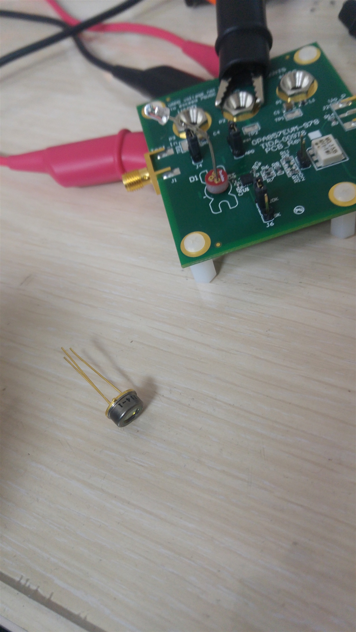
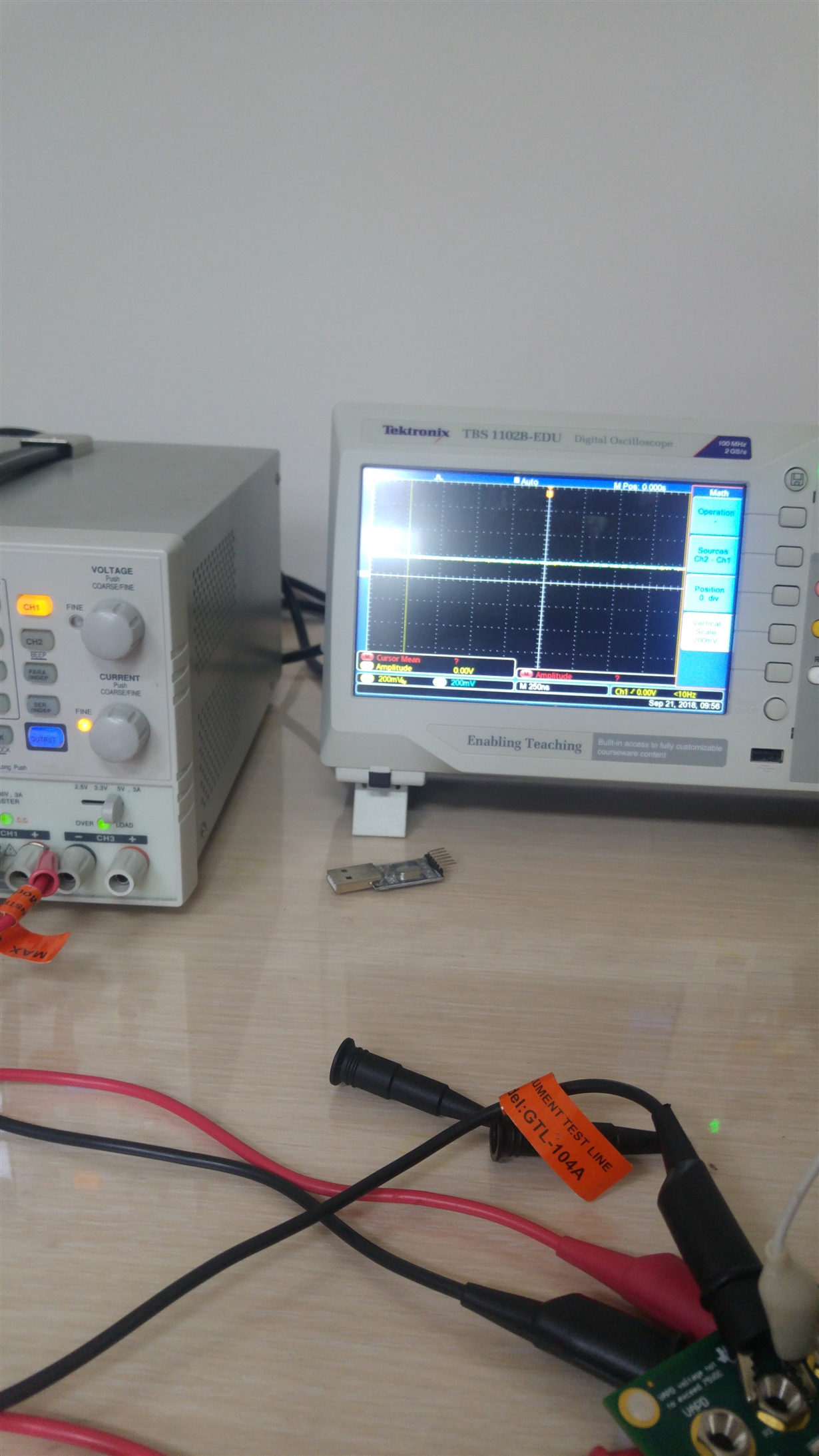
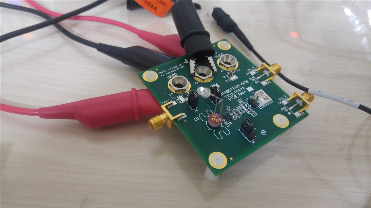
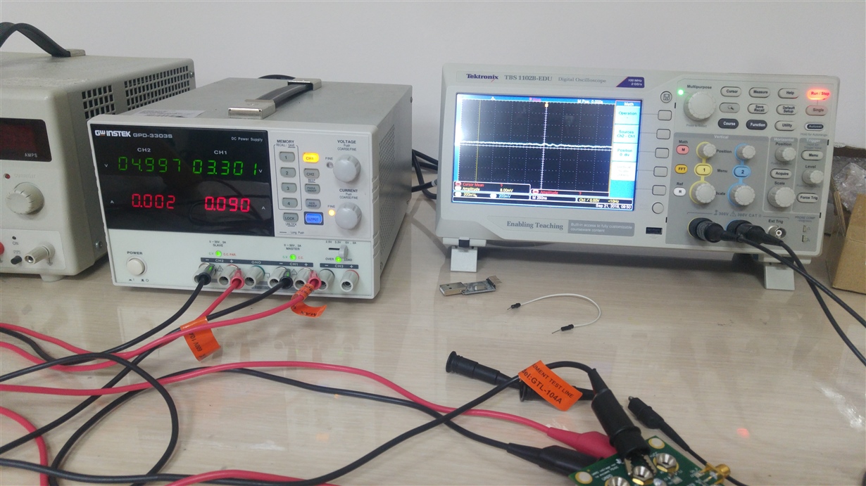
    İn the First Picture My way of measurement is showing. And I will use the photodiode that in the corner but for now I am trying to measure with a standard photodiode. And I have made standard TIA  on the breadboard and I take some measurements.

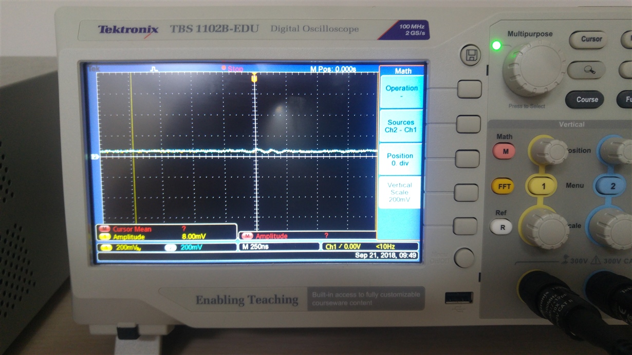
    İn the second picture there is 2 oscilloscope probe connected but as I move my source to the photodiode the voltage drop of R6 And R7 change exactly the same. and I have obtained when I close the photodiode there is a voltage drop of 0.108 V and when I close the source there is a 0.21 V. the other pictures are informative. and My board take 90mA current when I open the J4 it draws 28 mA current. And when I try to measure R8 when I move my source there is absolutely no change in the voltage drop and it always seems like 0.

    And I have tried to obtain J3 and J4 differential configuration but there isn't any change(I have connected  load of 500 ohm as indicated in datasheet).

    I couldn Understand what is the problem. There is a change but there is an absouletly same change in the resistors. I think thats why I cannot get any differantial output but How is it possible the votage drop change exactly same. 

    Thanks in advance.

  • Hi Ali,

    there are several issues:

    1. At low frequencies (<<0.4MHz, have a look into the datasheet of transformer) the transformer looks like a short circuit. The EVM board is designed for very short and narrow laser light pulses with signal frequencies in the MHz range and well above.

    2. The photodiode is too weak. The photodiode current is too small because the detetcor area is too small.

    3. It's quite normal that across R6 and R7 the same voltage drop can be observed, because the transformer is driven differentially via R6 and R7. But you will notice that the polarity is reversed.

    Again, what is the frequency signal range of your application? What pulses do you want to detect? What is the rise time, the amplitude, the fall time and the pulse width of your pulses? What is the total period of your waveform?

    Kai
  • Hi Kai;

    Yes I am trying to measure 10 ms and 100ms pulses just for results but later on I will try to measure 70 ns pulses if the board can detect those signals. But isnt it possible to detect only one pulse with really short pulse width?

    My bigger Photodiode has a bigger area and can detect quite well but I have tried it too but I couldnt measure anything from the transformer.

    3. Okay this answer a lot of question for me.

    My rise time is about 50 ns and amplitude can go to 300 mV with my breadboard application. Fall time is almots 70 ns. For now I am diffrerent periods from 1ms to 100 ms . But again No luck getting any signal out of it.

  • Hi Ali,

    I don't think that 10...100ms pulses can be seen at the output of transformer. 10ms pulse time (or 20ms period time) means a fundamental of only 50Hz. This far away from the 400kHz minimum frequency of output transformer. For your tests you should choose much faster pulses. Pulse times in the range of 1µs would be appropriate.

    Kai
  • Hi Kai;

    I have tried every possible frequency over the 400 khz but the transformer doesnt give any output?

    There is ony noise but I even eliminated them but there is no luch. I have tried 1 mhz pulse to 10 mhz pulses.

    Do you have any suggestions? Before the transforer there is a good response but when it comes to the transformer I cannot see any output.

    Thanks in advance

    Best regards.