hi,
Can i get more details ( including circuit calculations) on below circuit for stable voltage reference ?

This thread has been locked.
If you have a related question, please click the "Ask a related question" button in the top right corner. The newly created question will be automatically linked to this question.
hi,
Can i get more details ( including circuit calculations) on below circuit for stable voltage reference ?

Hello Paul,
I am using this circuit to generate DC offset reference voltage of 1.65 V for my ADC measurement ( Current of 11mA to 6A). Currently i am using MCP6L01 op-amp which i needs to be replaced with TI device (If gain peaking remains unsolved). While performing RS test (IEC61000-4-3) on my board, where radiations of freq range 80 MHz to 1 GHz are used, my reference voltage shows peaking in freq range of 110 MHz to 150 MHz. Which is causing shift in my DC offset resulting in wrong ADC measurement. If i remove cap of 100pF between input pins of opamp, same peaking is observed for 110 MHz to 300 MHz. For rest of freq range , ref voltage remains stable.
Kindly suggest me the design Aid.
Below is my Circuit diagram:
Hi Praful,
the best cure against radiated interference is to add a shielding. Just take a piece of metal, connect it to a suited signal ground and cover the susceptible circuitry.
In any case, your circuit is unstable and needs to be modified. Also, as Paul already mentioned, the 100p cap between the inputs of OPAmp heavily erodes the phase margin and can cause instability and oscillation.
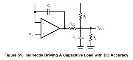
I would give the following circuit a try:
The phase stability analysis assuming an open loop output impedance of OPAmp of up to 2k shows, that this circuit can work in combination with an OPAmp with a unity gain frequency of under 1MHz. But if you take a faster OPAmp, C3 should be omitted!
Kai
Hi Praful,
as your OPAmp is from microchip and I only have limited data I have done a simplified phase stability analysis. Because your OPAmp draws only very little supply current I have assumed a worst case open loop open impedance of 2k. With the given components this results in a phase margin of 34° at 2kHz and 86° at 100kHz. So, the circuit should run stably:
Kai