This thread has been locked.

If you have a related question, please click the "Ask a related question" button in the top right corner. The newly created question will be automatically linked to this question.

AMC1311: Start-up Issue

Part Number: AMC1311

Hi Team,

My customer is using our AMC1311 as a current sense amplifier on their HV line. They currently faced issues in their start-up. Can you help comment on below inquiry:

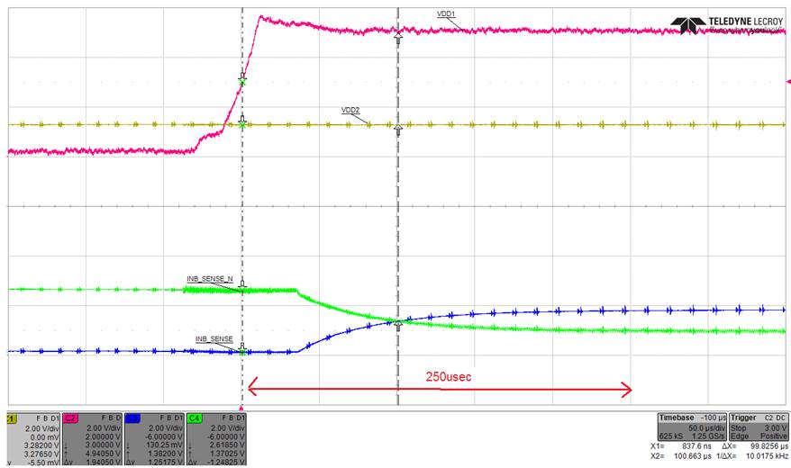
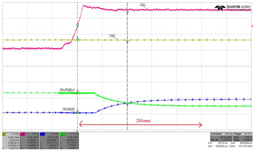
At start-up, the AMC1311 is going into the “Fail-safe Output” when the supply voltage Vdd1 is still missing.

What will be the worst case delay from Vdd1 present to Output of AMC1311 in stable condition?


In the specs the settling time Max is 100usec. However based on our captured waveform the output becomes stable at around 250usec.

 

Thanks!

Best Regards,

Alfred

  • Hi Alfredo,

    can you add a scope plot with shows also the input voltage Vin during turn-on? R15 times C24 gives a time constant of 330µs...

    Kai

  • Hi Kai,

    I only got feedback now. Below is the waveform with Vin.

    Do let me know if this was what you were looking for.

    Thanks!

    Best Regards,

    Alfred

  • Hi Alfred,

    hmm, I'm totally confused now! What are we seeing in the plot? The slowly changing curves at the bottom are no longer INB_SENSE and INB_SENSE_N?

    Kai
  • Hi Kai,

    See below more detailed description.

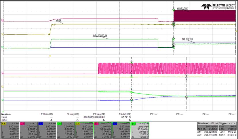
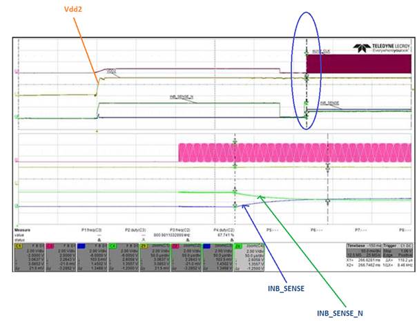
    The Green and Blue waveforms are INB_SENSE and INB_SENSE_N. It is the zoomed portion on the circled part of the waveform.

    The Voltage on the Input side of the AMC (Vin) is already stable by the time Vdd1 turns ON. In fact VDD2 is the output of our internal Auxiliary circuit that takes its input on the same Vin that the AMC measures. As you could see VDD2 is well stable, roughly 250msec before VDD1 turns-On.

    Thanks!

    Best Regards,

    Alfred

  • Hi Alfred,

    Have you gotten any further with this? What is that signal on Vin? I see the voltage divider in your schematic and expected to see a DC signal on Vin, which it sort of looks like in the first plot above, but then it seems to rail to GND and then oscillate after VDD1 comes up. If that is how your Vin signal really looks, what is the frequency? I suspect it's significantly higher than the 275kHz bandwidth of the AMC1311 and what you see on the outputs is the settling time though the forth order filter caused by the high frequency input. The 50uS settling time specification in the AMC1311 datasheet is based on a 3V DC step on the inputs.
  • Hi Tom,

    Pls can you clarify which waveform you are referring to?

    Is it the first waveform that I sent and that the oscillation you are pointing out is the one circled below?

  • It was the one from Oct 4th with the arrows pointing to IN_B_SENSE and IN_B_SENSE_N, it included VDD2 and what I thought you were calling VIN.