This thread has been locked.

If you have a related question, please click the "Ask a related question" button in the top right corner. The newly created question will be automatically linked to this question.

OPA2376: Startup malfunction

Part Number: OPA2376

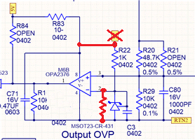
We use OPA2376 as a precise comparator to trigger over voltage protection.

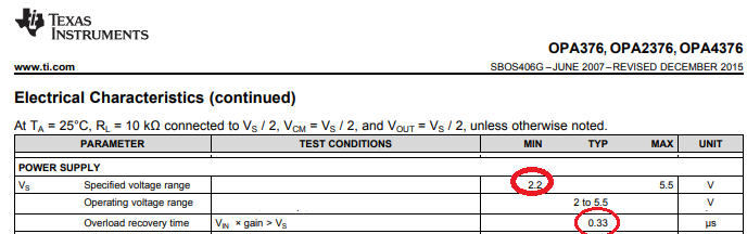
Pin3 is the voltage input pin. Pin2 is the 2.5V reference pin.

If pin3 voltage bigger than pin2 2.5V, pin1 should output high.

As the waveform below,

When start up at -30degC, even if pin3 < pin2, pin1 would output high signal.

If we turn off Vcc and restart, the pin1 output  would be much higher and make our circuit malfunction.

We try to change some OPA2376 and find out some has this issue at -10degC, some has until at -35degC.

Please help to figure out how the issue happen and how could we avoid it?

Thanks

  • Hi Wei,

    can you show a schematic?

    Do the input voltages exceed the supply voltage during power-on? Have you limited the input currents? Do the input voltages violate the common mode input voltage range at any time during power-on?

    Hmm, maybe you should allow the OPAmp some time to stabilize after power-on...

    Kai
  • Wei,

    Until the minimum supply voltage of 2.2V is met, OPA2376 does NOT work linearly and depending on the internal random offset voltage of multiple gain stages the output voltage level may be at either rail.  For that reason, you may not rely on the output being at the "correct" rail (regardless of actual voltages at the input terminals) until the supply voltage is above 2.2V and output has time to recover from overload condition - see below.

  • The Sch and Waveform(re-scaled to 1V/div) are as below.

    The input voltages, Vo(goes up slow) and 2.5Vref(created from Vcc 5V), may not be over Vcc during power-on.

    And the input currents are limited by resistors. 

    It's hard to wait for till power-on cause the over voltage protection should still be workable even when startup.

    Please help. Thanks.

    C1 OP-      C2 OP+     C3 OP out     C4 Vcc(5V)

  • I am not sure if the issue is with the min supply 2.2V,
    because the malfunction op output begins after Vcc over 2.xV and recover after about 50us when Vcc is about 3.5V.
    According to the spec, if it's overload, the recovery time may not too far from 0.33us?
    Thanks.
  • Hi Wei,

    it's not unusual that an OPAmp produces an erroneous output voltage spike during power-on. Nevertheless, I think that the voltage at the -input is a bit too high. I would try the following modification:

    Instead of the added resistor in parallel to the 431 you could even use a voltage divider formed by two resistors to furtherly reduce the voltage at the -input of OPAmp. Additionally you could add a RC low pass filter to the output to suppress the erroneous output voltage glitch.

    Another option is to use a true comparator instead of an OPAmp.

    Kai

  • Wei

    We haven't heard back from you so we assume this answered your question. If you need additional help just post another reply below.

    Thanks
    Dennis