This thread has been locked.

If you have a related question, please click the "Ask a related question" button in the top right corner. The newly created question will be automatically linked to this question.

CMVR test circuit


Hi,

I have a question about CMVR test circuit like this one (page16 of SNOA475D).

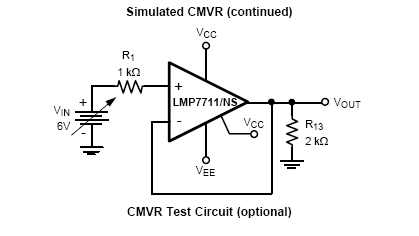
This test circuit is to test the CMVR but how we can differentiate CMVR and output swing with it?

I explain : If my output swing max is 12V and my input voltage range is 13V for example, when VIN will be equal to 12V output will saturate and so I can't test my input voltage range so how I do that and what I'm missing?


Thanks

  • Bonjour Matthieu,

    hmm, if the output saturates at 12V, then I would say the common mode input voltage range is only 12V and not 13V, as 12V is the input voltage where the output begins to saturate, by other words, where the OPAmp begins to leave its linear region.

    Kai
  • Hello Kai,

    But Op amp could have different specifications for input voltage range and output swing so with the circuit above, I don't know which specification I'm testing (between input voltage range and output swing).
    For me, this circuit works only if output swing is greater than input voltage range and if we measure this last one.

    Matthieu
  • I recommend you look at the op amp tutorial below that discusses in better detail CMV limitation versus output swing limitations:
    3. TI Precision Labs - Op Amps: Input and Output Limitations

  • Hello Tim,
    I already look this tutorial which are very nice.

    Nevertheless, I will try to ask again my question in a different way.

    If I would to test independently Input voltage range and output swing of a Spice model for an OpAmp (just because it is easier than in the real world) without having the datasheet, how I do that?

    With circuit above from SNOA475D because we have a follower, I can't tell if my issue (when I'm in nonlinear region) is from input voltage or output swing.

    Thanks
  • The way to measure the input common-mode voltage range is to place the circuit in a difference amplifier configuration (and not follower) with all four resistors matched (e.g. 1k), inputs shorted, and output referenced to ground.
    Thus in your example, with +/-15V supplies, applying +/-30V on the left of the matched shorted input resistors will result in the Vcm (directly at the op amp input terminals) being swept +/-15V and monitoring the output will give you linear common-mode range - output should stay around zero (2*Vos) for as long as the input Vcm is within its linear range - see below.

  • Ok, that sound very nice. So in the SNOA475D, there is a mistake or at least it's missing some precisions.

    Thanks Marek