This thread has been locked.

If you have a related question, please click the "Ask a related question" button in the top right corner. The newly created question will be automatically linked to this question.

LM258: Wierd behavior

Part Number: LM258
Other Parts Discussed in Thread: LM158-N, OPA2170, TL062, TLV2170

All,

I will try to explain as clear as possible:

I created a PCB where a microcontroller will read 2 analog inputs. For the analog inputs I use the LM258 as voltage follower. To protect the input I used a 10kOhm resistor and a TVS.

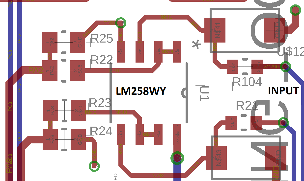
Because my microcontroller uses 5 V I use on the output of the opamp a voltage divider 7/1. As VCC on the LM258WY is 24V (not 12V as on the schematic below)

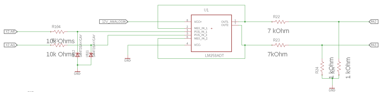
Now when I switch the source on. My output ( pin1 and 7 ). already give an output of 24V. The input voltage (pin 3 and 5) is 0V.

When I connect 20V to the input I get a short in the system and I burn the LM258.

I don't get what is going wrong. 

I simulated the system with an LM258AD (works fine in multisim)and I use a LM258WY. But I don't see in the datasheet that this would be the issue.

Could somebody please explain me what is happinng. I don't get it.

Thanks in advance,

Kind regards,

Toon Mertens

  • Hi Toon,

    TI doesn't produce the LM258WY, that looks like an ST Micro part.

    It's odd that you're getting 24V on the output when the power supplies are turned on and the inputs are 0V. Have you inspected your PCB for manufacturing defects?

    -Paul

  • Hi Paul,

    Thanks indeed. I first wanted to use the LM258AD but it wasn't available anymore with our supplier.
    I checked the pcb and can't see any manufacturing error at the first sight.

    I will keep you updated.

    Thanks for the quick response,
    Kind regards,
    Toon
  • Hi Toon,

    I also do not see any problems with the schematic or layout.

    Does the output rail to 24V when the *power* is applied? Or when the "source" is enabled? Does "Source" = Power Supply in the above?

    What is the input doing before the 20V input is applied? How are you applying the 20V? What is the expected input voltage range?

    The LM258 has a PNP input stage, so bias current flows OUT of the input pin (about 10nA current flows from V+, out the input and towards GND). So a 'floating" or high impedance input will naturally "float" up towards V+. That may explain why the output immediately rises to 24V if the output is left "floating" (unconnected).

    But when you probe the input with your DMM oe scope, you shunt the input to ground with the 10M input impedance of the DMM and the input then drops to "0V" (actually around 100mV). Are you seeing 0.000V on the input, or around 100mV? Watch the output as you probe the input and see if it drops.

    Can you go into detail about "When I connect 20V to the input I get a short in the system and I burn the LM258"??

    Is it immediate smoke? Just getting hot? Package cracked? Does it recover? What happens if you sweep up from 0V to 20V?

    Are you using the Unidirectional ("A") or Bi-Directional("CA") version of the TVS? You should use the Unidirectional "A" version to immediately clamp any negative voltages. Are you sure you are not accidentally applying -20V? These devices do not take well to negative input voltages.

    Are you sure the surface mount resistors are the values you expect? Double-check...
  • Hi Toon,

    sounds very strange... The 24V supply voltage, does it come directly from the plant? Is it this sort of supply voltage which is highly contaminated with switching noise, inductive kick backs, dips, spikes and transients? The supply voltage which comes from hell? :-)

    Or is it the vehicle's voltage of a truck? This voltage can be even more contaminated with transients and spikes!

    In this case you should urgently provide some protection circuitry for the supply voltage of OPAmp.

    As Paul already mentioned: The TVS is a SM4T28CAY? This would be a bidirectional TVS. Not good. A unidirectional TVS is better suited at the inputs of LM258.

    Kai
  • Hi Paul,

    The output rails to 24V when the power supply is switched on.

    So first:

    I desoldered the opamp, switched on the power and I measured every pin of the opamp.

    1. 0V
    2. 0V
    3. 0V
    4. 0V
    5. 0V
    6. 0V
    7. 0V
    8. 24V

    So this tells me allready there is no problem in the pcb.
    After I resoldered a new opamp onto my pcb and switched the power on again. Then I measure the following values on the pins:

    1. 21.24V
    2. 21.24V
    3. 0.276V
    4. 0V
    5. 0.264V
    6. 21.24V
    7. 21.24V
    8. 22.55V

    I supply the PCB with a normal bench power source. (ISO tech IPS303DD).

    Now I probed the input and output signal. Now indeed the output drops from 20V to 0V when I probe the input.
    So could you please explain me what the problem is here? How can this happen and how I should solve this?

    Please don't tell me I need to put a shunt resistor on my pcb. then I need to change it.

    Thanks for your support!
  • Hi Kai,

    Thanks for the reply.
    Paul helped me to figure it. when I measure with the osciloscope on the input the output drops aswell.

    Now I just need to find a solution.
  • Hi Toon,

    an input bias current is flowing out of the +input pin of LM258. Have a look at figure 16 of this datasheet to see why:

    www.ti.com/lit/ds/symlink/lm158-n.pdf

    This input bias current searches for a current path to signal ground. But because there's only a TVS, it biases this TVS until it opens. This will be at about 20...24V, according to the datasheet of TVS. This is why you measure 21.24V at pin 1, pin 2, pin 6 and pin 7.

    When you connect the meter at the +input of OPAmp you provide a current path for the input bias current to signal ground via the meter. 50nA causes a voltage drop of abput 0.5V across the meter impedance of 10M. That's why you measure 0.276V at pin 3 and 0.264V at pin 5.

    When you probe both, input and output, at the same time you will see that output drops because you short circuit the input with the probe impedance. Is it 1M? 50nA times 1M is only 50mV. So, you will see about 0V at the input and at the output. Disconnect the probe from the input and you will see the output rising again.

    Kai
  • Hi Kai,

    Thanks for the explaination. You made a clear for me. So to solve this issue the only way is by placing a resistor with high resistance in parallel with the TVS. That means that I need to refabricate the PCB.

    Work all the Opamps like this? Otherwise I could maybe search for an other opamp which doesn't have this?

    Thanks again for the good support.
    Kind regards
  • Hi Toon,

    it depends on what you connect to the input. If the input is driven by a low ohmic source, then a current path to signal ground for the input bias current is also provided and everything is fine.

    Yes, all OPAmps have input bias currents which must see a current path to signal ground.

    Kai
  • Hi Toon,

    For a high voltage voltage-follower, you could choose a newer CMOS op-amp like the OPA2170 or TLV2170. The TL062 might also be a good choice.

    Hope that helps,
    Paul
  • Hello Toon.

    The LM258 input bias current is about 20nA so the input will be pulled high. At most temperatures, LM258 bias current is greater than TVS diode leakage so input will be high.

    With TLV2170, the input current should be lower than the leakage of TVS diode so the input will go low. How low, I can not say. Open inputs can also easily pickup noise.